3i. When things don't work: Lamp Matrix
-
Lights controlled by the CPU (not the General Illumination lights), are
controlled in a similar fashion as a switch matrix. That is, there
are eight lamp rows, and eight lamp columns. This gives a total of
64 CPU controllable lamps. These lamps are powered by 18 volts.
This voltage is strobed (turned on and off very quickly),
and hence the final power to the lamps is about 6 volts.
|
Lamp matrix of 8 rows and 8 columns. |
|
The lamp columns are controlled by TIP42 transistors that switch the 18 volts on and off many times within a second. The lamp rows are controlled by TIP122/102 transistors that switch the ground on and off. Because the TIP42's source the current (instead of sinking the ground like a TIP122/102), lamp column TIP42 transistors go bad more often than TIP122/102 lamp row transistors.
The most common CPU Controlled Lamp Problem.
The most common controlled lamp problem occurs when the fuse blows
(with the blue/white wires) that connects
to the large 30,000 mfd capacitor and the bridge in the backbox.
If this happens, ALL the CPU controlled lamps will not work!
Check these three components for problems which would cause this fuse to fail.
Overly Bright Lamps.
When a transistor or diode goes bad, generally it shorts on. When a transistor
shorts on in the lamp matrix, it will make all the
lamps in that row or column appear permanently on, and be very bright.
This happens because the
lamp matrix is actually 18 volts that is continually turned
on and off, a row or column at a time.
This nets a lower +6 volts that the lamps require.
The lamps are never allowed to get full brightness at 18 volts
before being switched off. If a transistor has
shorted on, a row or column of lamps will be turned on for a longer
time, and hence be brighter.
All the computer controlled lamps in the lamp matrix should flash in attract mode, or in the "All" lamps diagnostic test. If a number of lamps remain on (and they aren't general illumination lamps), there may be a lamp matrix transistor problem.
If a number of lamps are out, check the bulbs and fuses first. If a number of lamps are stuck on, check the game manual and see if they are in the same row or column. If so, test the individual transistor (see the Testing Transistors and Coils section) before replacing it.
|
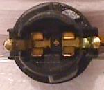
Left: 44/47 lamp, socket and the orientation of the diode. Note the banded end of the diode goes to the "middle" lamp lug. The non-banded end goes to the lamp's top lug. Right: The playfield socket used for 555 lamps. The small metal tabs on the outside of the socket often get bent. This prevents a good connection to the board on which they plug. Bend them back for better contact. |
 � �
|
|
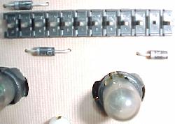
Left: the component (lamp) side of a lamp board. Note the diodes mounted to the board, and the use of 555 bulbs. Right: the solder (socket) side of a lamp board. Note the Molex header pins soldered here. Often these Molex pin solder joints crack or become fatigued, preventing the lamp(s) from working. |
 � �
|
- Remove the backglass.
- Turn the game on.
- After the game boots, for games Frankenstein and before, press the green button inside the coin door into the down position. Then press the black button to enter diagnostics. Press the black button to move through the different tests. For portals games (Baywatch and Batman Forever), press the black diagnostic button, and use the flipper buttons to go to the diagnostics icon. Then press the game's start button.
- Go to the "All" lamps diagnostic test.
- Unplug the connectors at CN6 and CN7 (lower middle portion of the CPU board).
- Connect an alligator test lead to pin 1 of CN6. Pin 1 is the right most pin, as facing the board.
- Connect the other end of this test lead to one lead of a 555 light socket. Temporarily get one of these from a playfield lamp (make sure it has a working bulb first).
- Connect another test lead to the second lead of the 555 light socket.
- On the other end of the test lead, clip on a 1N4004 diode, with the non-banded end away from the alligator lead. Touch the non-banded end of the diode to pin 1 of CN7 (the columns plug). Again, pin 1 is the right most pin, as facing the board.
- The lamp should flash.
- Move the diode/alligator lead on CN7 to the next pin. Again, the lamp should flash.
- Repeat the previous step, until the last pin of CN7 is reached.
- Remove the backglass.
- Turn the game on.
- After the game boots, for games Frankenstein and before, press the green button inside the coin door into the down position. Then press the black button to enter diagnostics. Press the black button to move through the different tests. For portals games (Baywatch and Batman Forever), press the black diagnostic button, and use the flipper buttons to go to the diagnostics icon. Then press the game's start button.
- Go to the "All" lamps diagnostic test.
- Unplug the connectors at CN6 and CN7 (lower middle portion of the CPU board).
- Connect the alligator test lead to pin 1 of CN7. Pin 1 is the right most pin, as facing the board.
- Connect the other end of this test lead to one lead of a 555 light socket. One can be temporarily borrowed from a playfield lamp (make sure the lamp works first!).
- Connect another test lead to the second lead of the 555 light socket.
- On the other end of the test lead, clip on a 1N4004 diode, with the banded end away from the alligator lead. Touch the banded end of the diode to pin 1 of CN6. Again, pin 1 is the right most pin, as facing the board.
- The lamp should flash.
- Move the diode/alligator lead on CN6 to the next pin. Again, the lamp should flash.
- Repeat the previous step, until the last pin of CN6 is reached.
- Remove the backglass.
- Turn the game on.
- Game can be in "attract" mode, or in the Test menu's "ALL" lamp test.
- Unplug the connectors at CN6 and CN7 (bottom portion of the CPU board).
- With the logic probe connected to power and ground, probe each pin 1 to pin 9 of CN6 (pin 1 is the right most pin, as facing the board). These are the lamp rows (return). All pins should show PULSE (low) on the logic probe.
- With the logic probe connected to power and ground, probe each pin 1 to pin 9 of CN7 (pin 1 is the left most pin, as facing the board). These are the lamp columns (drive). All pins should show PULSE on the logic probe.
- Bad bulb. Any light bulb can burn out. Often the bad bulb can be seen, but sometimes not. Test the bulb with a DMM, set to continuity. Put the test leads on the bulb. No continuity, and the bulb is bad.
- Wire broken away from the socket. This happens quite often and requires re-soldering the wire back to the socket lug.
- Diode broken away from the socket. If the lamp diode becomes disconnected from its socket, the lamp will not light.
- Corroded or Bad Socket. Games imported back into the US from other countries exhibit this problem more often. Re-seating the bulb in its socket often fixes this problem. On 555 plug-in sockets, bend the contact tabs slightly for better contact.
- Blown Fuse. If many GI lights don't work, check the fuse associated with them. If all the CPU controlled lamps don't work, check the F2 fuse by the big 30,000 mfd capacitor bolted to the back of the backbox.
- Burned Connector on the power supply or interconnect board. This happens most often with GI (general illumination) lamps. See Burnt GI Connectors for more info.
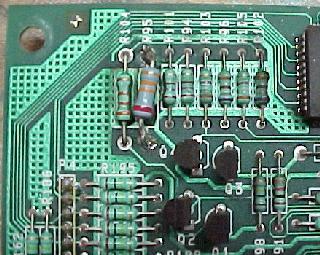
- Lamp matrix power resistors. On the CPU board, lower right corner, there are eight 0.4 ohm, 3 watt wire wound sand resistors (R55 to R62). Sometimes these resistors get hot and de-solder themselves from the CPU board and fall off (or the solder joints need re-soldering).
- Bad Column Transistor. The TIP42 transistors that control the lamp matrix columns often fail. If this is the case, all the lamps in a particular column will be brightly lit all the time.
- Two Lamps act as One. If a lamp diode has a shorted on, this can cause two different lamps to act as one.
- On the top side of the playfield, make sure the bad switch contacts haven't been bashed together by an errant "air" pinball.
- On micro-switches, check the actuator arm. Make sure it's adjusted properly. Listen for the micro-switch's "click" when activating. No click usually means the switch is mis-adjusted or broken.
- Check that the wires going to the switch are soldered well, and haven't fallen off.
- Check the continuity (using the DMM's continuity setting) of the daisy-chained wire between this switch and another working switch in the same column (green wire) or row (white wire).
- If it's a blade or leaf style switch, check the contacts for proper closure. Clean the switch contacts with a business card (do NOT use a file as the contacts are gold plated). Put the card between the contacts, close the contacts, and pull the card through the contacts once or twice. This is all that is needed to clean gold plated switch contacts.
- Check the switch to make sure it works. Use the DMM's continuity setting, and put one lead on the "common" lug (the lug to which the banded end of the diode connects) of the switch. Put the other lead on the green (normally open) switch lug. The meter should only beep when the switch is activated, and not beep when the switch is de-activated. Move the DMM's lead from the green to the white wire (normally closed) switch lug. The meter should beep when the switch is de-activated, and NOT beep when activated.
- Check the diode on the switch. Make sure the diode is connected properly, and is working (see "bad switch diode" or "fail safe diode test" below).
- Check other switches in that switch's row or column. Two 4041 chips control rows, and 2N3904 transistors and 74LS244 at 8J control columns. Both rows and columns are controlled by a 6821 PIA at 8H.
- Disconnect the middle green (ground) wire from the switch. It should have a quick connector. If the middle green ground wire is soldered to the switch, ignore this test and do the above "fail-safe" diode test.
- Put the DMM on diode setting.
- Connect the black lead of the DMM to the diode's banded side, and the red lead to the non-banded side.
- Activate the switch.
- A reading of .4 to .6 should be seen.
- Reverse the DMM's leads (red lead to the diode's banded side), and keep the switch activated. A null meter reading should be shown.
- Leave the leaf switch's diode and all wires connected.
- Make sure the switch isn't activated.
- Put the DMM on diode setting.
- Connect the black lead of the DMM to the diode's banded side, and the red lead to the non-banded side.
- A reading of .4 to .6 should be seen.
- Reverse the DMM's leads (red lead to the diode's banded side). A null meter reading should be seen.
|
Testing a diode on a lamp socket circuit board. The black lead is on the banded side of the diode. |
|
-
Lamp Diodes.
Each CPU controlled lamp will have a diode associated with it. If this diode is bad (shorted on), it will cause other lamps in that row or column (or even another row or column) to turn on. This can be seen in the "All" lamps test. The faulty row or column will light TWICE in a single lamp matrix sweep (once when it should be on, and a second time due to the short on ANOTHER row or column re-lighting it). The lamp(s) in question are on twice as long as all the other CPU controlled lamps.
If a lamp diode has broken (become open), or is disconnected from the lamp socket, its lamp will not light.
Two Lamps On Instead of One.
If a lamp diode is shorted on (or installed incorrectly), this can cause
two lamps to act as one. This can be seen in the "Single" (or "One") lamp test.
Each individual lamp in the
lamp matrix (as displayed on the screen) should flash.
The "start game" button will move the test from one lamp to another.
If TWO lamps flash in this test instead of just one, suspect the chosen
lamp has a bad or mis-installed lamp diode.
-
Testing a Lamp Diode.
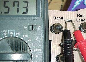
In order to test a lamp diode, use the DMM set to diode test. Turn the game off and put the black test lead on the banded side of the diode. A reading of .4 to .6 volts should be seen. Reverse the leads and put the red lead on the banded side of the diode. A null reading should be seen. Any other reading and this lamp's 1N4004 diode should be replaced. To perform this test, the light bulb does not need to be removed, or the diode desoldered. The diode soldered to the circuit boards that hold the 555 lamps can also be tested in the same manner.
|
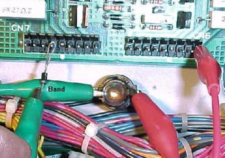
Testing the lamp matrix columns using two test leads, a 555 socket (pulled temporarily from the playfield), and a 1N4004 diode. One test lead is attached to pin 1 of CN6 on the CPU board, and is stationary. The other end is attached to the lamp socket. Another test lead is connected to the second lead of the lamp socket. A diode is clamped to the other end of the test lead. Then the non-banded side of the diode is touched to each pin of connector CN7. In the "all" lamps test the lamp should flash for each pin. |
|
Testing the Lamp Columns.
If a TIP42 transistor that drives a lamp column is suspected as bad,
test it:
If a lamp column tested doesn't give a flashing test lamp, that column is bad (or the test diode is reversed!). No light or a non-flashing, bright lamp are signs that the respective TIP42 column transistor is bad. Test the transistor as described in Testing Transistors and Coils.
|
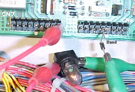
Testing the lamp matrix rows using two test leads, a 555 socket (pulled temporarily from the playfield), and a 1N4004 diode. One test lead is attached to pin 1 of CN7 on the CPU board, and is stationary. The other end is attached to the light socket. Another test lead is connected to the second lead of the lamp socket. A diode is clamped to the other end of the test lead. Then the banded side of the diode is touched to each pin of connector CN6. In the "all" lamps test the lamp should flash for each pin. |
|
Testing the Lamp Rows.
If a TIP122/102 transistor that drives a lamp row is suspected as bad,
test it:
If a lamp row tested doesn't give a flashing test lamp, that row is bad (or has the test diode reversed!). No light or a non-flashing, bright lamp are signs that the respective row TIP122/102 transistor is bad. Test the transistor as described in Testing Transistors and Coils.
Testing the Lamp Rows (returns); Alternative Method.
The lamp rows are controlled by TIP122/102 transistor at Q72 to Q79.
With the game in diagnostics test mode (menu or any test but the lamp tests),
run an alligator jumper wire from ground to the metal tab
on one of these TIP122/102 transistors. This will cause the entire lamp row to
light up.
Testing the Lamp Matrix Columns and Rows with a Logic Probe.
If a logic probe is available, it can be used to easily test the lamp
matrix:
The Lamp Matrix Power Resistors.
On the CPU board at the lower right corner, there
are eight 0.4 ohm, 3 watt wire wound sand resistors (R55 to R62).
Sometimes these resistors get hot and de-solder themselves from
the CPU board and fall off (or the solder joints need to be re-soldered).
If there is a lamp matrix problem and it's not the row or column
transistors, make sure you check these resistors.
Most Common Problems with Lamps.
I replaced the Offending TIP122 and TIP42, and I've check the Lamp
Matrix Power Resistors, but the Lamp Matrix still
doesn't Work Right.
It is rare, but problems in the lamp matrix can occur further up stream.
For the lamp matrix columns, transistors Q56 to Q63 are 2N6427 transistors which drive the TIP42 column transistors. Sometimes these can fail too. Before the 2N6427 transistors are two 7408 TTL chips at 9F and 10F which drive the whole circuit. These all connect to the 6821 PIA at 11D. Any of these components could fail too.
For the lamp matrix rows, 7406 TTL chips at 11F and 12E drive the rows though a series of 2N5060 (NTE5400) silicon controlled rectifiers at Q81 to Q88. These also connect to the 6821 PIA at 11D.
3j. When things don't work: Switch Matrix
-
Switches on any pinball game are very important. On electronic games, when a switch closes,
it informs the CPU to score points, award a feature, and/or to activate a solenoid.
If a switch is stuck closed, the CPU will ignore this switch
(in most cases).
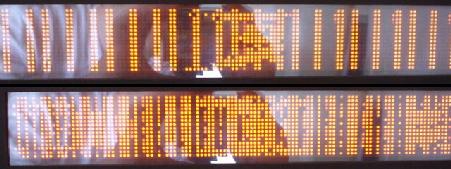
If a switch is not activated in 50 games, or is permanently closed, the switch is assumed to be bad. This will create a test report, which is shown when the game is turned on (this feature was implemented in DataEast games Phantom of the Opera and later). If a particular feature of a game is difficult to score, it's associated switch may be (falsely) assumed bad (if not activated in 50 games). To correct the test report, remove the playfield glass, and activate the switch by hand within a game, or within the diagnostics switch edge test.
|
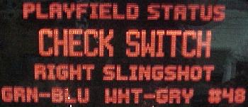
A switch report, shown when the game is turned on. |
|
-
All switches on a DataEast/Sega game (except for the direct switches at
connector CN14, which
are the test button switches), are in the "switch matrix".
The switch matrix is controlled by eight switch columns, and
eight switch rows. The cross-section of any row and column designates any
one of the potential 64 different switches.
The switch columns (drive) are controlled through CPU board connector CN8, which connects to 2N3904 transistors Q48-Q55. The output of these goes to the resistor network (4.7k x 8) RA11. This then goes to the 74LS244 chip on the CPU board at 8J. The output of this chip then goes to a 6821 PIA at 8H.
The switch rows (return) are controlled through CPU board connector CN10, which connects to resistor network (560 ohm x 8) RA16, which in turns goes thru resistor networks RB5 and RB6 (1k x4). This in turns connects to 4011 chips at 5J and 6J. This then connects to the same 6821 PIA at 8H.
|
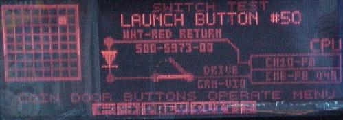
Switch diagnostics (Baywatch and later) have become very informative. This is the switch test known as "TST". Shown is the switch wiring, CPU connectors, wire colors and even the switch's column (drive) transistor (Q49). |
|
-
Test Button Switches.
The test button switches inside the coin door are wired directly to the CPU board at connector CN14. These switches do not go through the switch matrix. The test button switches are direct switches to the CPU board. The diagnostic switch connects to the CPU's NMI line. DataEast did this so when there is a switch matrix short, the user can still get into the game's diagnostic tests without using any switches in the switch maxtrix.
Shorting the Switch Matrix to +50 volts.
When hurried, it is tempting to make an under playfield adjustment
with the game turned on. Doing a switch adjustment with the power on
could easily short a coil lead (+32/50 volts) to a switch lead.
This will immediately blow the switch matrix, and fry
most anything to and including the 6821 PIA at 8H.
It is also a likely the switch row 4011 chips at 5J and 6J will fail.
Also it could take out any of the switch column 2N3904 transistor(s) Q48-Q55,
and the 74LS244 chip at 8J.
After replacing the suspected CPU board components, disconnect the switch input plugs from connectors CN8 and CN10 at the bottom of the CPU board. Put the game into switch test mode, and none of the switches should be activated on the display! If a whole row of switches is still activated, this would indicate something in the CPU circuitry is still bad.
Shorting the Flipper EOS switch to the Lane Change switch.
Many games have a feature called "lane change".
This allows the player to change the lit lanes using the cabinet flipper
buttons. Prior to Robocop, this is done by doubling up a second switch on the flipper
EOS switches. The EOS switches are a +50 volt switch. The lane change switch is a
+5 logic switch connected to the switch matrix. These two switches are
insulated from each other by a small nylon "triangle" activator. But if
these two switches touch, the switch matrix will burn (as
described above).
|
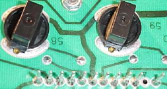
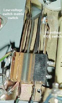
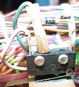
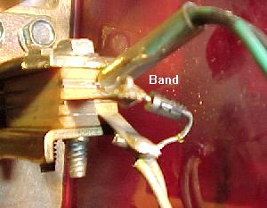
Games Monday Night Football and before: the EOS flipper switch on these games is actually two switches. The switch on the left (with the diode) is low-voltage and connected to the switch matrix. This normally open switch closes when the flipper is activated, and controls the lane change and high score initials. The switch on the right is the high-voltage flipper EOS switch. A nylon space insulates the two switches from each other. |
|
When adjusting or cleaning the flipper EOS switches or lane change switches, make sure the game is turned OFF. This will prevent shorting these two switches together. Also, do not clean the smaller lane change switch with anything other than a business card.
Lane Change on games with Solidstate Flipper boards.
When the solidstate flipper system was introduced on Robocop, DataEast stopped
using a doubled up switch on the flipper EOS switches for the lane change.
The lane change switch was moved to the cabinet flipper switch.
This was done because the cabinet flipper switch on solidstate flipper games
was a low voltage switch. This meant there was less potential switch matrix problems
with the switch located here instead.
Switch Numbering.
Each switch has a number associated with it. The
switches are just numbered 1 to 64. There is no relationship between the switch
number and what row or column the switch number belongs. For example, switches 1 to 8
are column 1, rows 1 to 8. Likewise, switches 9 to 16 are column 2,
rows 1 to 8. This continues up to switches 57 to 64, which are
column 8, rows 1 to 8. This is unlike Williams' WPC games, where
switch 42 means column 4, row 2.
Using the Internal Switch Tests.
To test switches, use the internal test software. On Frankenstein and before,
press the green button inside the coin door down, then press the black button.
Pressing the black button again will move from test to test. Go to the
switch level ("TST") test.
On Baywatch and Batman Forever, just press the black diagnostic button inside
the coin door to enter the service portal. Use the flipper buttons to scroll
to the "diag" icon, and the game's start button to select it.
Then go to the switch level "TST" test.
Activate any switch on the playfield using a pinball (this simulates
real game play), and it should show on the
game's display.
If a Bad Switch is Found.
If a switch does not work, check these things:
If the switch is bad, replace it. If all the switches are bad in a particular switch column or row, chances are good the problem is not the switches themselves (CPU board problems).
|
Switch matrix of 64 switches: eight rows and eight columns. |
|
-
Switches are "Daisy Chained".
If a switch does not work at all, or a series of switches do not work, remember to check the "daisy chain". Switch wires are connected in series. That is, if a switch wire in the same row or column breaks off a switch "up stream", it can make all the switches connected to it "down stream" not work. Make sure you check the wire "daisy chain" for any breaks if a switch (or several switches) do not work.
Phantom Switch Closures: a Shorted Switch.
It's a strange problem. During game play, the ball
goes down the right inlane, and the left slingshot fires! Or when a
ramp shot is made, the game slam tilts. One switch closes, but a
completely unrelated event then occurs.
This is a classic description of a shorted switch. It confuses the switch matrix into thinking something else has occurred. This can happen from an "air" pinball, that bashes an above playfield switch's contacts together, causing a short. Also a bad switch diode can do this. In either case, the shorted switch must be found. Unfortunately, it won't be obvious. The switch matrix is confused, so any diagnostics the game provides will be of limited help.
First, try to find the switch that causes something unrelated ("phantom") occurance. Take the playfield glass off, and start a game. Activate the switches with your hand, and find the switch which activates the phantom (unrelated) switch. Once the switch is found, go to the game manual and find the switch's number, row number, and column number. Say for example, switch 53 (column 7, row 5) is causing the phantom closure. Now get the other three switches that make up the remaining corners of the "square" of the row and columns. First get the reverse switch number, switch 39 (column 5, row 7). Then get the other two "corner" switches: switch 37 (column 5, row 5), and switch 55 (column 7, row 7). The switch short will probably be one of these four switches.
If there are problems figuring out if the short is in the playfield or the CPU board, try this. Remove connectors CN10 and CN8 from the CPU board. Next put the game in switch edge test. Using the manual, find which row and column of the switch that causes the phantom closure. Then cross this row and column directly on the CPU board (with wire and alligator clips, and a diode, as described below in the "Testing the Switch Columns/Rows"). The row and column numbers for each pin of connectors CN10 and CN8 are listed below. If the phantom switch does not activate, the problem is in the playfield. If the phantom closure still works, there is a CPU board problem.
If the phantom switch problem is on the CPU board, don't forget to look at the 1k ohm x 8 resistor pack RA6 on the CPU board. When this resistor pack goes bad, it can cause intermittent phantom switch closures. Use the DMM, and test the resistor pack. If in doubt, just replace it.
Bad Switch Diode.
Each micro-switch on the playfield also has an 1N4004 diode soldered to
it. This diode can short closed. It doesn't happen often though.
Important: If a switch diode does short closed, all switches in that particular column or row will exhibit strange behavior. If a switch diode goes permanently open, the switch will never register. Keep this in mind when diagnosing switch matrix problems.
Fail-Safe Diode Test.
With the game off, use the DMM set to diode
position. With the black lead on the banded
side of the diode, it should show a .4 to .6 volt reading. Reversing the leads
should show a null reading. If the diode tests bad,
cut one lead of the diode from the switch to remove it from the circuit,
and test it again just to make sure the diode is really bad.
Replace the diode if bad, or reconnect the diode after testing.
|
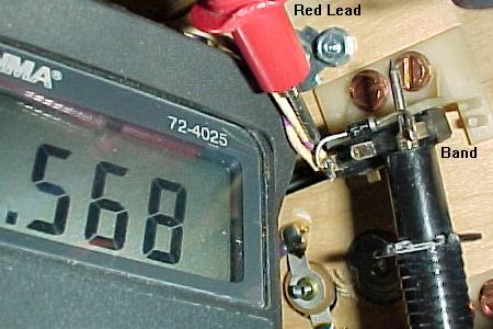
Testing a switch diode on a microswitch without removing the diode. The switch must be activated, and the middle green wire (ground) must be disconnected. |
|
-
Testing a Microswitch's Diode, without removal.
The diode on a microswitch can be tested without unsoldering a diode lead from the switch. This technique assumes the switch is wired in the standard configuration: green (ground) wire to the center lug, the banded end of the diode to the far switch lug, and the non-banded diode lead and the switch wire(s) to the close switch lug (as shown in the picture above).
Testing a Blade/Leaf Switch's Diode.
Testing the diode on a leaf switch is far easier.
No wires need to be disconnected, and the switch should not
be activated. This technique assumes the switch is wired in the standard
configuration: green (ground)
wire to the center lug, the banded end of the diode solo, and the
non-banded diode lead and the switch wire(s) to the other switch lug (as shown
in the pictures below).
Installing a New Switch Diode.
Replace the diode with a 1N4004 (or 1N4002 or 1N4001)
diode. Make sure to install the new diode with its band in the same orientation
as the old diode (assuming it was correctly installed in the first place,
which isn't always a good assumption). If unsure, compare
the diode's band orientation to a working switch and diode. Most (but not all!)
switches have the green (ground) leads connected to the center (normally
open) lead of the switch. Then the row (white) wire is connected
to the switch lead closest to the center lead (the normally closed lead).
The banded end of the diode is connected solo to the far (common) switch leg,
and the non-banded end is connected to the same leg as the row (white) wire.
There are some exceptions to this mounting. The game manual should specify
any non-standard switch installations.
|
Notice the orientation of the diode's band on these switches. On a micro-switch, the ground (green) wire usually goes to the center lug, the "live" wire and the non-banded side of the diode to the lug closest to the center. The band on the diode goes to the solo, far third switch lug. The leaf switch uses the same connection method (ground to center, banded end of diode solo). Note there are some exceptions to this mounting. |
 � �
|
- Pin 1 = Column 1, green/brown
- Pin 2 = Column 2, green/red
- Pin 3 = Column 3, green/orange
- Pin 4 = Column 4, green/yellow
- Pin 5 = Column 5, green/black
- Pin 6 = key
- Pin 7 = Column 6, green/blue
- Pin 8 = Column 7, green/violet
- Pin 9 = Column 8, green/gray
- Pin 1 = Row 8, white/gray
- Pin 2 = Row 7, white/violet
- Pin 3 = Row 6, white/blue
- Pin 4 = key
- Pin 5 = Row 5, white/green
- Pin 6 = Row 4, white/yellow
- Pin 7 = Row 3, white/orange
- Pin 8 = Row 2, white/red
- Pin 9 = Row 1, white/brown
- Remove the backglass.
- Turn the game on.
- After the game boots, go to the diagnostic menu's switch levels or "TST" test.
- Unplug the connectors at CN8 and CN10 (bottom portion of the CPU board).
- Connect an alligator test lead to pin 9 of CN10. Pin 9 is the left most pin, as facing the board.
- On the other end of the alligator test lead, clip on a 1N4004 diode, with the banded end away from the alligator lead. Touch the banded end of the diode to pin 1 of CN8 (pin 1 is the right most pin, as facing the board).
- The display should show switch 1 is closed.
- Move the diode/alligator lead on CN8 to the next pin. The display should show switch 9 is closed.
- Repeat the previous step, until pin 9 of CN8 is reached. Switches 1, 9, 17, 25, 33, 41, 49, 57 should be closed on the display as the lead is moved forward, pin 1 to pin 9, on connector CN8. Note pin 6 is a key pin, and should be skipped.
- Remove the backglass.
- Turn the game on.
- After the game boots, go to the diagnostic menu's switch levels or "TST" test.
- Unplug the connectors at CN8 and CN10 (bottom portion of the CPU board).
- Connect an alligator test lead to pin 1 of CN8. Pin 1 is the right most pin, as facing the board.
- On the other end of the alligator test lead, clip on a 1N4004 diode, with the banded end towards the alligator lead. Touch the non-banded end of the diode to pin 1 of CN10 (pin 1 is the right most pin, as facing the board).
- The display should show switch 8 is closed.
- Move the diode/alligator lead on CN10 to the next pin. The display should show switch 7 is closed.
- Repeat the previous step, until pin 9 of CN10 is reached. Switches 8, 7, 6, 5, 4, 3, 2, 1 should be closed on the display as the lead is moved forward, pin 1 to pin 9, on connector CN10. Note pin 4 is a key pin, and should be skipped.
- Remove the backglass.
- Turn the game on.
- Game can be in "attract" mode, or in the Test menu's "Switch Levels" test.
- Unplug the connectors at CN8 and CN10 (bottom portion of the CPU board).
- With the logic probe connected to power and ground, probe each pin 1 to pin 9 of CN8 (pin 1 is the right most pin, as facing the board). These are the switch columns. All pins should show PULSE on the logic probe.
- With the logic probe connected to power and ground, probe each pin 1 to pin 9 of CN10 (pin 1 is the left most pin, as facing the board). These are the switch rows. All pins should show HIGH on the logic probe.
-
Switch Matrix Row or Column Problems: the Easy Test.
If the game is giving an error message regarding a switch matrix row or column problem, determine if this is a CPU board problem or a playfield problem. The easiest way to do this is to unplug the switch matrix row and column plugs at CN10 and CN8. Enter the game's diagnostics (coin door green button down, press the black button), and go to the switch edge test. If the row or column problem is gone (no switch reports), the problem is in the playfield wiring. If the problem is still there, the problem is on the CPU board. Be aware that most shorted switch matrix problems are caused by a bad switch matrix column 2N3904 transistor at Q48-Q55 (which affects the entire column).
Switch Matrix Plug and Pin Numbers.
When doing intensive switch matrix diagnostics with the
plugs removed at CN10 and CN8, simulate an actual
playfield switch closure, without using the playfield! This can
be done by using the internal switch edge test, and an alligator
lead connected to the particular row/column (switch) in question,
and a diode (as described above).
CN8 Switch Column (drive) Pin Numbers
CN10 Switch Row (return) Pin Numbers
|
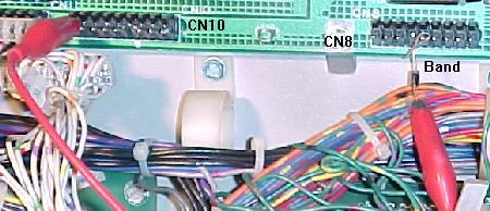
Testing the switch matrix columns: Using a diode and a test lead, the test lead is attached to pin 9 of CN10, and is stationary. The other clip holds the non-banded side of the diode. Then the banded side of the diode is touched to each pin of connector CN8. The "switch levels" test should indicate switches 1, 9, 17, 25, 33, 41, 49, 57 when moved from pin 1 to 9, respectively. |
|
-
Testing the Switch Columns (drive).
To test the switch columns, do the following:
If a particular column number does not display as closed, or is closed without any test lead connection, there is a problem on the CPU board. Usually this is a bad switch matrix column 2N3904 transistor at Q48-Q55.
|
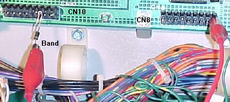
Testing the switch matrix rows: Using a diode and a test lead, the test lead is attached to pin 1 of CN8, and is stationary. The other clip holds the banded side of the diode. Then the non-banded side of the diode is touched to each pin of connector CN10. The "switch levels" test should indicate switches 8, 7, 6, 5, 4, 3, 2, 1 when activated. |
|
-
Testing the Switch Rows (return).
To test the switch rows, do the following:
If a particular row does not display as closed, or is closed without any test lead connection, there is a problem with the CPU board.
Testing the Switch Matrix Columns and Rows with a Logic Probe.
If a logic probe is available, it can be used to easily test the switch
matrix:
Resistor Network Testing/Explaination used in the Switch Matrix.
The resistor networks in the switch matrix can fail, and this is fairly
common. There are two types of resistor networks used on the DataEast/Sega
CPU board; "Bussed" and "Isolated".
If a resistor network is "560 x 8" and has 9 pins, that means it's BUSSED; all the resistors are tied to one common pin (this pin is labeled with a white square around it on the circuit board). Bussed resistor networks are labled as "RAx" (where "x" is a number). Simply put, if a resistor network has an odd number of pins, it is probably bussed.
If a resistor network is "1K x 4" and has 8 pins, this is an ISOLATED resistor network; a bunch of resistors in the same small package, so it uses two pins per resistor. Isolated resistor networks are labeled as "RBx" (where "x" is a number). Simply put, if a resistor network has an even number of pins, it is probably isolated.
| Left: A bussed resistor network. Right: An isolated resistor network. |
 � �

|
- RA16: 560 ohms x 8, bussed, used for the switch returns (rows).
- RB5/RB6: 1k ohms x 4, isolated, used for the switch returns (rows).
- RA6: 1k ohms x 8, bussed, used for the switch drives (columns).
- RA11: 4.7k ohms x 8, bussed, used for the switch drives (columns).
- 1k x 4 issolated (4 pins): Q4102-ND (discontinued)
- 1k x 8 bussed (9 pins): Q9102-ND (discontinued)
- 4.7k x 8 bussed (9 pins): Q9472-ND
- 560 x 8 bussed (9 pins): Q9561-ND
- 3.3k x 8 bussed (9 pins): Q9332-ND (discontinued)
- 1K x 4 resistors Isolated (8 pins), Bourns part# 4608X-102-102 (Mouser part# 652-4608X-102-1K). Digikey carries a very similar Bourns part# 4308R-102-102 (Digikey part# 4308R-2-102-ND).
- 1K x 8 resistors Bussed (9 pins), Bourns part# 4609X-101-102 (Mouser part# 652-4609X-101-1K).
- 4.7K x 8 resistors Bussed (9 pins), Bourns part# 4609X-101-472 (Mouser part# 652-4609X-101-4.7K).
- 560 x 8 resistors Bussed (9 pins), Bourns part# 4609X-101-561 (Mouser doesn't have stock but lists it as part# 652-4609X-101-560 or 652-4310R-101-560). If needed a 10 pin version of this part can be used and any additional pin cut off (make sure the correct pin is cut!), Bourns part# 4610X-101-561 (Mouser part# 652-4610X-101-560). .
- 3.3K x 8 resistors Bussed (9 pins), Bourns part# 4609X-101-332 (Mouser part# 652-4609X-101-3.3K or 652-4310R-101-3.3K).
- CN8 pin 1, to Q55, to R105, to RA11 pin 2, to 8J pin 18 (column 1).
- CN8 pin 2, to Q54, to R104, to RA11 pin 3, to 8J pin 3 (column 2).
- CN8 pin 3, to Q53, to R103, to RA11 pin 4, to 8J pin 16 (column 3).
- CN8 pin 4, to Q52, to R102, to RA11 pin 5, to 8J pin 5 (column 4).
- CN8 pin 5, to Q51, to R101, to RA11 pin 7, to 8J pin 14 (column 5).
- CN8 pin 6: KEY
- CN8 pin 7, to Q50, to R100, to RA11 pin 8, to 8J pin 7 (column 6).
- CN8 pin 8, to Q49, to R99, to RA11 pin 9, to 8J pin 12 (column 7).
- CN8 pin 9, to Q48, to R98, to RA11 pin 10, to 8J pin 9 (column 8).
- CN10 pin 1, to RA16 pin 2, to RB5 pin 1, to RB5 pin 2 (1000 ohms), to 6J pins 1 & 2 (switch row 8).
- CN10 pin 2, to RA16 pin 3, to RB5 pin 3, to RB5 pin 4 (1000 ohms), to 6J pins 12 & 13 (switch row 7).
- CN10 pin 3, to RA16 pin 4, to RB5 pin 4, to RB5 pin 6 (1000 ohms), to 6J pins 8 & 9 (switch row 6).
- CN10 pin 4: KEY
- CN10 pin 5, to RA16 pin 5, to RB5 pin 7, to RB5 pin 8 (1000 ohms), to 6J pins 5 & 6 (switch row 5).
- CN10 pin 6, to RA16 pin 6, to RB6 pin 1, to RB6 pin 2 (1000 ohms), to 5J pins 1 & 2 (switch row 4).
- CN10 pin 7, to RA16 pin 7, to RB6 pin 3, to RB6 pin 4 (1000 ohms), to 5J pins 12 & 13 (switch row 3).
- CN10 pin 8, to RA16 pin 8, to RB6 pin 5, to RB6 pin 6 (1000 ohms), to 5J pins 8 & 9 (switch row 2).
- CN10 pin 9, to RA16 pin 9, to RB6 pin 7, to RB6 pin 8 (1000 ohms), to 5J pins 5 & 6 (switch row 1).
- Switch column shorted to ground.
When a column wire is shorted to ground, and any switch in that column is closed, the switch test will show ALL switches in the ROW of the closed switch as being closed. If no switches are closed, the switch test will show no switches closed. To find the location of the short, go to the end of the switch column wire on the playfield (the switches are "daisy chained" together for an entire column or row). Then break the daisy chain one switch at a time until the short no longer shows in the switch test. - Row shorted to ground (diode anode).
When the anode (non-banded end of the switch diode) is shorted to ground, the switch test will show the entire row as activated (whether any switches are closed or not). To find the location of the short, go to the end of the switch row wire on the playfield (the switches are "daisy chained" together for an entire column or row). Then break the daisy chain one switch at a time until the short no longer shows in the switch test. - Row shorted to ground (diode cathode).
When the cathode (banded end of the switch diode) is shorted to ground, that switch's entire row will show as closed in the switch test (whether the switch is open or closed). To find the location of the short, go to the end of the switch row wire on the playfield (the switches are "daisy chained" together for an entire column or row). Then break the daisy chain one switch at a time until the short no longer shows in the switch test. - Column wires shorted together.
When two column wires are shorted together, and none of the switches in those columns are closed, the switch test will show no problems. But pressing any switch in either column will show that switch, along with a switch in the column that is shorted on the row of the switch being closed. For example, if column 2 and column 4 are shorted together, closing switch column 2 row 3 will also show a closed switch in column 4 row 3. - Row wires shorted together.
When two row wires are shorted together, and no switches are closed, the switch test will show no closed switches. When any switch in either row is closed, another switch on the same column as the closed switch will also show as closed. For example, if rows 1 and 4 are shorted, closing a switch in row 1 column 3 will also show a closed switch on row 4 column 3. - Column and row wires shorted together.
When a column and row wire are shorted together, the switch test will show the switch that is at the intersection of the row and column as being closed, even though it is not closed. All other switches on all other rows and columns will work correctly. For example, column 1 and row 3 are shorted together. The intersection of this column and row will show that switch as closed (even though it's not). And remember, this switch is not the cause of the problem! - Open diode on a switch.
An open diode on a switch will cause only that switch to not work. - Shorted diode on a switch.
A shorted switch diode will show no problems when only that switch is opened or closed. However if additional switches in that row or other columns are closed, false switch readings can be shown. - Micro-switch: no maintenance required. Can adjust the actuator arm only by rotating the switch in its bracket. Do not BEND the activator arm! Loosen the two screws holding the switch, and rotate the switch to adjust the activator arm. Re-tighten the screws, but not too tight as it will bind the switch mechanism.
- Blade or Leaf switch: clean with a business card inserted between the contacts. Squeeze the contacts closed, and remove the business card. Do not use a file on these gold plated contacts! Re-adjust the contact spacing for correct operation.
- Opto switches: use a Q-Tip and some Windex. Dip the Q-tip in the Windex, and clean the opto's two LED's (receiver and transmitter) with the Q-tip.
- With the game on, enter diagnostics, switch test.
- Block the optic light beam; does it repond in the test? If yes, the optic switch is OK. If no, continue...
- Visually inspect the optic transmitter; is it glowing red? If yes, than the transmitter is OK. If no, check pin 2 of the opto transmitter board for +5 volts. Remember the opto transmitter is doing nothing more than acting like a flashlight. If it is on, it is working!
- If the opto switch is still not working, remove the 2 pin connector with the green and white wires on the opto receiver board (the board that does NOT have the glowing LEDs). Using a jumper wire, short the two wires on this connector plug together. This should show the switch as closed in the switch test. If the switch does close with the short, there may be a bad alignment of the opto receiver and transmitter (this is a very common problem). If shorting these two wires together does nothing, suspect a broken wire in the switch matrix wiring.
- Size: 1 3/4 (T size) or 5mm.
- Illuminated Color: Red
- Lens Color: Clear
- Wavelength: 660
- View Angle: 10 to 12
- mA (max): 20
- Volts (typ): 1.7
- Volts (max): 2.5
- MCD (typ): 3000
- Checkpoint to Hook (128x16 dot display): Z80A CPU. This dot matrix controller is mounted right to the back of the dot matrix score display glass itself.
- Lethal Weapon to Guns N Roses (128x32 dot display): 68B09 CPU on a separate controller board mounted behind the display glass, #520-5055-00 (Leathal Weapon to Last Action Hero) or #520-5505-01 (Tales from the Crypt to Guns N Roses).
- Maverick to Batman Forever (192x64 dot display): 68000 CPU on a separate controller board mounted behind the display glass, #520-5092-01.
- J2 pin 1: +5 volts
- J2 pin 2: Ground (logic)
- J2 pin 3: KEY
- J2 pin 4: +12 volts
- J2 pin 5: +68 volts
- J2 pin 6: -98 volts
- J2 pin 7: -110 volts
- J2 pin 8: Ground (high voltage)
- J2 pin 9: Ground (high voltage)
- P1 pin 1: -110 volts
- P1 pin 2: -98 volts
- P1 pin 3: KEY
- P1 pin 4: Ground
- P1 pin 5: Ground
- P1 pin 6: +5 volts
- P1 pin 7: +12 volts (only used on Babcock displays)
- P1 pin 8: +68 volts
- P3 pin 1: +5 volts DC
- P3 pin 2: Ground
- P3 pin 3: Ground
- P3 pin 4: +24 volts DC. (Dale schematics show 24 volts, but 16-18 volts
is probably used, as the voltage originates from a backbox mounted bridge
rectifier BR1 or BR3 supplying 18 volts DC.)
DALE (only) component P1 voltages. Derived by the on-board power supply. The voltages are taken from the above connector P3 and through a small power supply, converted to the following:
- P1 pin 8: +80 dc
- P1 pin 2: -90 dc (vrw)
- P1 pin 1: -100 dc
- P1 pin 4: Ground
- P1 pin 5: Ground
- NOT INSTALLED.
Babcock (only) component P1 voltages. These are converted on the board to the +80, -90 and -100 volts DC needed for the display.:
- P1 pin 1: +12 dc
- P1 pin 2,3: Ground
- P1 pin 4: No connect
- NOT INSTALLED.
Cherry (only) component P2 voltages. These are converted on the board to the +80, -90 and -100 volts DC needed for the display.
- P2 pin 1,2: +12 dc
- P2 pin 4,5: Ground
- P2 pin 6: +5 dc
- Turn the game off.
- Lower the display panel on the game.
- Connect a (black) alligator jumper wire from either lead of capacitor C29 (near U15) on the back of the display glass' circuit board.
- Connect the other lead of the (black) alligator jumper wire to one of the row pins on the dot matrix glass. This connector puts -100 volts DC on the row the jumper is connected to. NOTE: there are two sets of row pins, on each side of the display glass. Each set corresponds to that half of the display glass.
- Connect a (red) alligator jumper to the banded side (cathode) of CR2 on the dot matrix display board (this is a connection to +68 volts DC).
- Put a 33k ohm 1/2 watt resistor in the free lead of the red alligator clip.
- Turn the game on.
- Touch the free end of the resistor (which is connected to the red alligator lead) to one column lead on the display glass. Note the column must be on the same half of the glass as the row connected!
- The dot which intersects the row and column should glow.
- Two 27020 EPROMs = R11 installed (display board part number 520-5055-00).
- One 27040 EPROM = R11 removed (display board part number 520-5055-01).
- 5 feet of #18 red wire.
- 5 feet of #18 black wire.
- 5 pin .156" molex plastic connector body.
- 8 pin .156" molex plastic connector body.
- (4) .156" molex connector pin, crimp style.
- Some heat shrink tubing.
- Remove the old connector from the Display control board connector J1. Remove the old connector on the Power supply board connector CN5, if present. These connector(s) will no longer be used.
- Use five feet of 18 gauge red wire, create a "loop". Connect the two ends of the wire together, and solder them. Use some heat shrink tubing to insulate the wire jointing point. Repeat this with the 18 gauge black wire.
- On one spot of the red wire loop, strip back the insulation about 1/4 inch without cutting the wire. Bend the wire in the middle of this stripped area. Crimp a .156" molex connector pin to this point. Carefully solder the wires to this connector pin after crimping. Repeat this on the wire loop 2.5 feet away (the two new pins are now directly opposite each other in the wire loop). Repeat this step for the black wire loop.
- Insert the one red wire and one black wire connector pins into the 5 pin plastic connector body. One red wire pin (+5 volts) goes to connector pin 1. The black wire pin goes to connector pin 3. Note that pin 2 is the "keyed" pin. Use the Display controller board connector J1 as a reference for the pin numbers.
- Insert the other red wire and black wire connector pins into the 8 pin plastic connector body. One red wire pin (+5 volts) goes to connector pin 8. The black wire pin goes to connector pin 2. Note that pin 7 is the "keyed" pin. Use the Power supply board connector CN5 as a reference for the pin numbers.
- Attach the new 5 pin molex connector body to the Display controller board connector J1. Attach the new 8 pin molex connector body to the Power supply board connector CN5.
-
Here are the different resistor networks used in DataEast/Sega switch matrix:
When testing a BUSSED resistor network, first find pin 1. This pin will have a white square around it, to isolated it from the rest of the pins. Use a DMM set to ohms, and put one lead on pin 1. Put the other lead on each pin 2 to 9. The same reading should be seen for each pin 2 to 9.
When testing an ISOLATED resistor network, put the DMM leads on the two adjacent pins furthest to the right or left, and note the reading. Then move both DMM leads down one pin. The same value should be seen. Continue down the resistor, moving both DMM leads one pin at a time, until all adjacent pins are tested.
|
A bussed resistor network on a DataEast game. Note the white square around pin 1; this is the common pin. |

|
|
A "hacked" bussed resistor network (same DataEast game as above). If the correct resistor network can not be found, this shows how to make a bussed resistor network from individual resistors. Note the white square around pin 1; this is the common pin. This picture shows quite well how a bussed resistor network is wired. Since some resistor networks are hard to get, this repair will get more and more common. |

|
-
Replacment resistor networks are (were) available from Digikey
(www.digikey.com),
but many have been discontinued by the manufacturer. Below
are the (some former) Digikey part numbers. The 4.7k x 8 bussed resistor network
is also available from Docent Electronics at
members.aol.com/_ht_a/espain5941/myhomepage.
Unfortunately 9 pin resistor networks are not very popular anymore. Usually everybody uses an even number of pins (6, 8, 10) even if it gives you an odd number of resistors (5, 7, 9). The even pin numbered devices are far easier to find than the odd pinned ones. Digikey seems to have dropped all 9 pin parts in favor of 8 and 10 pin parts. If really needed, can always buy 10 pin parts and cut off the 10th pin. Bourns seems to be the only common manufacturer of these now. Most are available from mouser.com.
Bad Switch Column (Drive): How to Diagnose/Fix.
Usually the switch column transistors fail. These are 2N3904 transistors
at Q48 to Q55. See the Checking Transistors
section for details on testing these transistors. Right before the transistors
there is a bussed resistor network at RA6 (1k x 8) which should be check
(as described above). After the resistor network is a serious of small
capacitor, C74 to C81 (these rarely fail). Next each one of the
eight 2N3904 transistors connects to a 1.5k resistor at R98 to R105. Then the
individual resistors connect to a bussed resistor network at RA11 (4.7k x 8). This network
can fail. A reading of 4.7k ohms for each connection should be shown:
Bad Switch Row (Return): How to Diagnose/Fix.
First check the 560 ohm X 8 bussed resistor network at RA16 (as described above).
Then check the two isolated 1k ohm x 4 resistor networks at RB5 and RB6 (as described above).
A reading of 1k ohms should be shown for each connection:
Jurassic Park Switch Matrix Problems.
On the game Jurassic Park,
one of the main playfield wire harness trunks can rub against the
upper right flipper coil stop. The vibration of the flipper coil can
cause the harness to saw against the coil stop, shorting the wiring.
This can cause random coil firing, blown fuses, and switch matrix
shorts. To fix this, first inspect the wires for any cuts or shorts.
Then resecure the wiring harness with nylon wire ties. Use
the ties to pull the wiring harness away from the coil stop.
This problem was discussed in service bulletin number 53.
View this bulletin by clicking
here and
here.
Hook Erratic Slam Tilt Problems.
Intermittently Hook performs strangely, and occassionally "slam tilts"
or kicks solenoids for no apparent reason. This can be caused by a
intermittently grounded switch strobe line. Most often, this is caused
by the green wire with the yellow trace on the left drop target bank.
This wire gets pinched against the playfield support bracket. To fix this,
check this wire on the drop target, and make sure it is not pinched
by the support bracket. Dress the wire with electrical tape or
heat shrink tubbing, and a tie wrap, to prevent future occurances.
This problem was discussed in service bulletin number 37.
Further Diagnosing of the Switch Matrix.
If there is a switch matrix problem, the first plan of
attack is to do the above column and row switch matrix tests.
If these tests pass, the problem most likely is in the wiring.
Note most switch failures show as row failures (even though it
could be a column problem). Here are several
different ways the switch matrix can fail. All require the use of
the internal "switch level" or "switch edge" or "TST" tests of the game.
Switch Maintenance.
Here are the procedures for maintaining the switches:
3k. When things don't work: Ball Trough Problems & Optic Switches
-
Sega didn't start using optic switches until the game Maverick. Before this,
all switches were the mechanical type. With Maverick, Sega for the first
time used an optic switch on the "Paddle Boat Wheel". Two games later,
Sega started using optics in every game, in the ball trough.
Opto Overview.
Sega designed their optic system to operate just like a standard
switch. Blocking the light beam caused the normally open opto switch to respond
by closing the switch, just like a mechanical switch (and unlike
Williams' optic switches, which are normally closed).
Sega used ultra-bright visible red light LEDs (Light Emitting Diodes), so
an opto transmitter's light can be seen with the naked eye (again, unlike Williams
which used infrared light that cannot be seen with the naked eye).
These ultra bright optos have a narrower bandwidth too, so ambient light
has little affect on them (again, unlike infrared LEDs).
Because of this, troubleshooting is easy:
Ball Trough Optics.
Starting with Baywatch, Sega added a single LED (light emitting diode) and opto receiver
above position one of the ball trough (to sense that the ball has been kicked to the
playfield shooter lane).
Replacement Optics.
The opto transmitters (the part that most often fails) are available at
Radio Shack, part number 276-087 or 276-066 (a high-brightness red LED).
Unfortunately, it seems these two Radio Shack part numbers have been
discontinued. But Radio Shack part number 276-307 also seems to work
fine. Other LEDs could probably work too. The specs needed are:
A Major Opto Board Problem.
Problems with the opto's themselves are rare. A much more common problem
is cold/fatiqued solder joints on the small PCB which holds the optic circuit. The LED's
are mounted to two small 2"x2" boards, with several surface mounted transistors.
Because the ball trough takes a lot of abuse from the
balls falling into the trough, it is very common to see cold or fatiqued solder
joints on ball trough optic boards.
Often the solder joints on the connector head pins and the surface mounted parts fatique (crack),
from the constant jarring of the balls in the trough. This can cause intermittent
(or complete) failure of ball trough sensing. To fix this problem,
use a low heat solding pencil, and reflow the solder on these surface mounted
transistors. Though the components are small, this can be easily done.
Also reflow the solder joints on the header connector pins
on these small boards.
|
The surface mount components on the ball trough optic board. These tiny components can get fatigued (cracked) solder joints from balls constantly slamming into the ball trough. |

|
-
Opto Service Bulletin.
Sega put out a good service bulletin (number 67) on how their optos work. If none of the above information has helped, check out there opto information here, here, and here.
Later Whitestar system Sega games use TWO optics in the ball trough. The second set of optos is used to verify a ball is actually plunged to the ball shooter lane. This system still has the same fatiqued/cracked solder joint problem on the optic's PC board.
Roller Switch Ball Troughs (Jurassic Park and later).
Starting with Jurassic Park, all
DataEast/Sega games used a five or six ball trough with a roller micro switch
for each ball. These switches can get damaged very easily from balls dropping on them. If
any one of these switches does not work properly, the game will not work correctly.
Error reports such as "ball missing" or multiple balls served to the plunger
lane are common problems.
Luckily, these switches are easily replaced with a common Radio Shack part number 275-017 ($1.99).
Often the problem with these roller micro switches is the last one or two balls to enter the ball trough will not activate their respective switch. If the switch is not moving freely, or the switch's roller not working perfectly, the ball may not roll onto the switch (activating it). If the switch cannot be adjusted to fix this, replace it. Do not try to lubricate the switch! Just replace the switch.
Testing the Ball Trough Roller Switches.
Most of the games with the 6 ball trough roller switches have a feature
in the diagnostics called "Easy Trough Clear". Upon entering this diagnostic
feature, pressing a flipper button will shoot one ball from the trough
into the shooter lane. The dot matrix display should show how many balls
the game thinks are left in the trough. By doing this, one ball at a time,
a defective switch or balls that don't roll down the trough are pretty easy to identify.
After all the balls are cleared from the trough, go to the switch test. Make sure each roller switch activites in the switch test. If more than one switch is shown to activate with a single roller switch, there is some sort of switch matrix short or a mis-wired switch. This can confuse the game and cause problems. See the switch matrix section of this document for more details.
The Ball Trough Roller Switch Diodes.
Remember there is a diode on each ball trough roller switch. It is possible
for these diodes to get broken, crushed or shorted when the playfield is lowered
from a raised service position. Keep this in mind too.
"Six Balls Missing" Error on JP.
Another problem seen, for example on Jurassic Park, is the message
"six balls missing". Clearly not all six ball trough switches are broken!
Instead, transistor Q54 (on Jurassic Park) has failed. The lock ball assembly coil (mounted
under the ball arch on the top side of the playfield) has its red wire (32 volts)
located very close to the mounting screw for the ball trough assembly. This creates
a potential short, causing transistor Q54 to fail. To prevent this, make sure
the solder lug on the coil is insulated from the ball trough mounting screw using
electrical tape or heat shink tubing.
This problem was discussed in service bulletin number 53.
View this bulletin by clicking
here and
here.
Three Ball Troughs (Laser War to Rocky & Bullwinkle).
Prior to the roller switches, DataEast games (Rocky & Bullwinkle and prior)
used large micro switches with long metal activator arms. This ball trough
system was limited to three balls maximum. Problems with bent or broken
ball activator arms are common on this ball trough system.
|
A five ball trough with the five roller switches. |
|
3L. When things don't work: Score Display Problems
-
DataEast was the first company to introduce the dot matrix display on a pinball
game in 1991 ("Checkpoint"). This first DataEast display is known as the "small DMD",
with 128 vertical lines and 16 horizontal lines. Williams followed with their
introduction of Terminator2, but used the "normal DMD", which was 128 by 32 lines. DataEast's
first "normal DMD" was Lethal Weapon, in June of 1992. Then in
September 1994, DataEast one-up'ed Williams again with the "super-size DMD", at 192 by 64 lines,
on their pinball Maverick.
This display only lasted for four games (Maverick, Frankenstein,
Baywatch, and Batman Forever) because of cost issues.
The "normal" DMD (128x32) is by far the least expensive of the three displays (about $125 street price). The small (132x16) display sells for about $165, and the super sized (192x64) display sells for over $200 (that's why DataEast/Sega discontinued it's use).
Display Service Bulletins.
For more information on dot matrix score displays, check out DataEast's service
bulletin number 50 by clicking
here and
here.
For more information on alpha-numeric score display (as used on Laser War to
Simpsons), check out Sega's service bulletin number 87. It explains the
entire theory of operation for these displays. For this service bulletin click
here and
here.
"Outgassed" Score Displays.
Score display glass has a limited life; it does not last forever.
Time will eventually kill these, and the display will "outgas"
and fail. Because of the high voltage involved with score displays,
the anode and/or cathode inside the display glass breaks down. This results in the "outgassing"
of impurities that eventually change the internal gas properties, so the display
can't glow (the gas must be very pure for the display to work).
There is no fix for this other than replacing the display glass (which
has become fairly expensive now). Outgassing affects dot matrix
displays very often, but it also applies to alpha-numeric displays too (see the alpha-numeric
section below for more details).
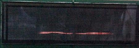
An outgassed score display puts much higher electrical loads on the power supply. When a display starts to outgas, it should be replaced immediately! Otherwise, the repair may involve fixing a damaged (burnt) power supply, in addition to replacing the score display glass.
|
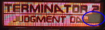
The blue circle shows a dot matrix display that is outgassed. |
|
-
Outgassed displays are easy to spot, especially on dot matrix displays.
The display needs time to "warm up" before
all display dots are working (visible). When initially powered on, an outgassing
display will only partially work. The corners and edges of the display are
first affected when a display is starting to outgass. In a few minutes, as the gas inside the display
warms up and expands, often the blank areas of the display will start to appear.
Even in this stage, when the display is fully working in a few minutes, the
score display glass should be replaced immediately. Otherwise the power supply can be
damaged by too much stress on the high voltage section.
Dot Matrix Displays (DMD).
The Dot Matrix Controller Board's CPU and PAL Chips.
DataEast/Sega games Checkpoint and later with a dot matrix
display have a dot matrix controller board. This board
has separate CPU and EPROM chips which only handle the dot matrix
score display animations. This CPU is in addition to the
CPU board's 6808 (or 6802) CPU chip, which controls the lamps, solenoids,
switches, games rules, etc.
The 128x32 dot matrix controller #520-5055-00 and 520-5055-01 uses two custom PAL chips at U2 and U16. Both of these chips are very static sensitive, and can fail if the board is mis-handled (U16 seems to be more problematic of the two). The PAL code is available here for download, if a PAL programmer is available. For location U2, a TIBPAL16R4-25 chip is needed (code checksum 50D8). For location U16, a TIBPAL16L8-15 chip is used (code checksum 6489).
Voltages Needed for the DMD Controller Board.
Since all the dot matrix displays essentially have their own
computer on the controller board to control the score display, a supply of good +5 volts is
needed for the controller. If a display is not working, first
check the controller board for +5 volts. Often the connector carrying +5 volts
can gain resistance, which will lower the +5 volts. This can be enough to make the DMD not work
(this problem happens most with the super-sized 192x64 DMD).
The display itself is a complete separate unit, and does not get voltage from the display controller. On the super-size 192x64 DMD, the input voltages are low (+5 volts and +12/18 volts coming into the display). Sega did this because the 192x64 DMD has it's own power supply on the dot matrix controller board itself (the higher voltages are not supplied by the main power supply). This is unlike the other two smaller dot matrix displays.
WARNING: on small and medium dot matrix displays, the power plug on the glass display board itself is the *same* type of plug. But do NOT connect a small dot display to a medium display power source (or vice versa)! It will RUIN the display if this happens, as the pinout is *not* the same!
Listed below are the other voltages required for the three different DMD displays, and the pin out. All voltages should be within 10% plus or minus of the numbers listed below:
-
Small 128x16 DMD, connector J2:
Medium 128x32 DMD, connector P1:
DALE Super-Size 192x64 DMD, connector P3:
Babcock Super-Size 192x64 DMD, connector P3:
Cherry Super-Size 192x64 DMD, connector P3:
Small DMD Problems and Fixes.
A very common problem on the small 16x132 displays (as used on five games, Checkpoint to
Batman) is a failed R95 resistor. It is very common for this 33k, 1/2 watt
resistor to go out of spec, or even open. This will cause the display to look
garbled (see picture). Often the display itself is fine; it's just this resistor
that needs to be replaced.
|
The display on "Mutant Ninja Turtles" with a bad R95 resistor. |
|
|
The same display after R95 is replaced. |

|
-
When replacing the resistor, it is best to just cut the old R95 resistor
out, closest to the resistor itself. Then solder the new resistor to the old
"legs". It is very easy to tear the traces when removing the old
R95 lead. This technique will prevent that.
|
R95 is replaced here. |
|
-
If after replacing R95 the display is still garbled, check for torn
traces. The top lead of R95 connects to the top lead of R94.
The bottom lead of R95 connects to the top lead of transistor Q2.
If continuity is not detected between these points, replacing
R95 won't change anything until the torn trace(s) are repaired.
Vertical Lines in the Small DMD.
Another problem seen on the small DE dot matrix display is
vertical lines, which completely distort the images behind it.
|
The vertical line problem in small DMD displays. |
|
-
In this case, this problem was fixed by replacing the
display. Always replace R95 first on the display, and see if that fixes the problem.
If it does not, the next step is to try the display in another
small DMD DataEast game, to verify it is actually the display at fault.
In this case it was the display at fault, and the fix was to
buy a new display (though a display driver chip is probably at fault,
the easy, but expensive fix, was to replace the display).
Testing the Small Dot Matrix Display Glass.
Use this technique to test a new or used small (128x16) dot matrix score glass.
This technique uses an existing small dot matrix display panel to test a loose
dot matrix score glass. Here is the procedure:
128x32 DataEast Dot Matrix Display EPROM differences.
Depending on the age of the game, the dot matrix display may have either a single
27040 EPROM, or two 27020 EPROMs. If it is necessary to change the
number of EPROMs used in the 128x32 dot matrix display,
add or remove resistor R11 on the Display controller board (the board
that holds the display EPROMs). Here is the breakdown:
128x16 and 128x32 Dot Matrix Display "Failures".
On Checkpoint to Guns N Roses (all games with small 128x16
and mid-sized 128x32 dot matrix displays), there is a unique problem that can
make the game look very broken. Random horizontal lines
and garbage can be shown on the dot matrix display (but actually the game's CPU has booted
correctly and is working OK). On games with the small 128x16 displays, random horizontal
lines can appear first, followed by the entire display lighting and staying lit.
If the backbox 18 volt lamp matrix fuse (8 amp slo-blo, with the blue/white wire connecting to the fuse holder) fails, this can cause the dot matrix display to "crash", causing these problems. Another way to identify this problem is the lack of any playfield CPU controlled lighting. The game will "play" (that is, the game will start and play balls), but with score display problems and no CPU controlled lamps. Simply replacing this the 18 volt lamp matrix fuse (in the backbox) will fix this problem (providing the associated components such as the bridge and capacitor are OK). If there is a lamp matrix power short, or the lamp matrix backbox bridge is bad, the problem will need to be fixed or the fuse will continue to immediately fail.
This problem occurs because the +12 volts needed for the dot matrix display is generated by the 18 volt lamp matrix bridge and the capacitor/fuse bolted inside the backbox (through connector CN5 on the power supply). The 12 volts generated by the power supply board (for the sound board which comes from connector CN6), does not provide this voltage to the dot matrix display! Hence the power supply could be working perfectly, and this problem could still exist.
|
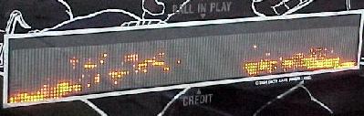
A Babcock 128x32 display where the 18 volt lamp matrix backbox fuse has failed. Notice the horizontal "garbage" line across the bottom center of the display. This problem only seems to affect the Babcock brand dot matrix displays. |
|
-
Interestingly, on 128x32 displays, this problem will only occurs on games with "Babcock" brand dot matrix
displays. The 128x32 displays made by Cherry and Dale seem unaffected by a failed 18 volt
backbox lamp matrix fuse. This happens because the Babcock displays require 12 volts
to function, where Cherry and Dale 128x32 displays do not. This problem can
also arise on Cherry brand 128x16 dot matrix displays.
This stange problem was solved with the advent of the 192x64 super-sized dot matrix display (Maverick to Batman Forever). An additional backbox 18 volt fuse (F3), bridge and capacitor was added. This backbox voltage supplied power to a switching power supply, implemented on the 192x64 DMD display driver board. This way if the lamp matrix (F2) fuse failed, the dot matrix display remained unaffected.
Super-Size 192x64 Dot Matrix Display Problems and Fixes.
On the four games (Maverick, Frankenstein, Baywatch, and Batman Forever)
with the super-size 192x64 dot matrix display, there have been some problems.
With age, the large dot matrix display may "blank out",
or cause the game to reset intermittently. The dot matrix display
controller board (#520-5092-1) has its own 68000 micro processor, which runs
at 12 mHz. It operates best with logic +5 volts right at 5.0 volts! Any
drop in voltage (to even 4.9 volts) can cause the display CPU to shut down
or reset. As these games get older, the connectors fatique, and small amounts
of resistance appear. Or the grounding strap going to the display
board can become loose. These problems can cause the +5 volts fed to the display to
drop enough to cause problems.
Also, when both flippers are simutaneously used during a game, the dot matrix display can reset, (but the CPU may not!). This will display the display board ROM revision level and the initial power-on sound board tones/speech.
Also be aware the large dot matrix display requires 120 nanosecond EPROMs or faster. If using 150 ns EPROMs (which are OK in the older 128x32 and earlier displays), the super size display will not work! The 68000 processor for the display is running at 12 mHz, so the 150 ns EPROMs are too slow.
There is an update kit available from DataEast/Sega/Stern for the large dot matrix display games. This kit is a wiring harness that goes directly between power supply and the large dot matrix display which runs the +5 vdc directly from the power supply to the dot matrix display. The kit is part# 500-6326-00, and costs about $11. The kit can be purchased from Stern, or self-manufactured (many distributors do not stock this kit). Also the kit can be made for much less than $11.
If you want to make your own 192x64 upgrade kit, the parts needed are:
Making and installing the 192x64 upgrade parts:
The above modification will give the large dot score display direct power, via brand new connectors, directly from the power supply. Note instead of using Power supply connector CN5, the present IDC connector at CN6 can also be used. The black wire can be inserted directly into the CN6 connector, pin 1. The red wire can be inserted directly into the CN6 connector, pin 10 (for reference, the key is pin 5).
View Sega's original service bulletin number 106 for this modification by clicking here and here.
If the Super Size DMD Still Doesn't Work...
Additionally, the +5/+12 volt bridge rectifier (DB1) on the power supply board
may need to be replaced.
If this bridge becomes "leaky" (less efficient), it may not be able to supply
the robust +5 volts needed on the display board. So if the above modification
does not work, replace bridge DB1 next.
When replacing DB1 on the power supply board, also
solder an 18 gauge wire from the "+" lead of bridge DB1 to the "+" lead
of capacitor C4. Solder another 18 gauge wire from the "-" lead of the
bridge DB1 (the lead diagonal to the bridge's "+" lead) to the "-" lead of capacitor
C1. Do this on the solder side of the power supply board.
These added wires will help prevent future cracked solder joints on
the power supply board.
Lastly, make sure the backbox grounding strap is tight and making good contact to the 192x64 dot matrix controller board. A loose grounding strap can contribute to super size DMD problems.
Important Notes on Installing a New 192x64 Dot Matrix Display.
192x64 DMD score displays often need a small modification to work
in the Sega games. This involves changing the supply voltage jumpers on the display
itself. On older 192x64 displays, there is no jumper, but
instead a trace is cut between the ribbon cable connector plug
and the P3 power plug (see picture below).
|
An older 192x64 dot matrix display with the supply power trace cut to work in Sega pinball games. Picture by Jerry. |
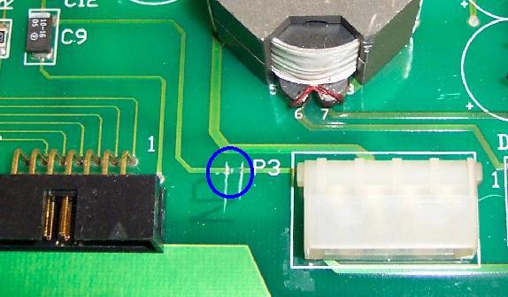
|
-
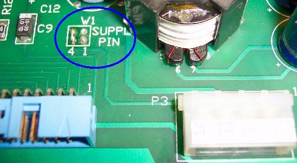
On newer 192x64 DMD score displays there is a jumper marked
"W1 Supply Pin". This jumper must be set correctly or the display
will not work in Sega pinball games. The two vertical "4" jumper
pads on the left should be tied together (see picture below).
|
A newer 192x64 dot matrix display with the supply power jumpers set to work in Sega pinball games. Picture by Jerry. |
|
- CN5 pin 1: Ground
- CN5 pin 2: Not used
- CN5 pin 3: -100 volts DC
- CN5 pin 4: +100 volts DC
- CN5 pin 5: KEY
- CN5 pin 6: +5 volts DC
- TR3 = MJE340 or MJE15030 transistor. The MJE340 is a NPN 300 volt transistor, and slightly more robust than the MJE15030 (but the MJE15030 is easier to find). Also a 2N3440 with a "star" heat sink will work.
- TR1 = 2N5401 (PNP 150 volt transistor).
- D6 = 1N5228 (3.9 volt 1/2 watt) or 1N4730A (3.9 volt 1 watt) diode.
- D9 = 1N4764 (100 volt, 1 watt) diode. Use 1N4763A (91 volt, 1 watt) diode instead (to increase score display life).
- R8 = 39k ohm, 1 or 2 watt flame proof resistor.
- R12 = 680 ohm, 1/2 watt resistor.
- R11 = 330k ohm, 1/2 watt resistor.
- C13 = 0.1 mfd 500 volt (or 250 volt will also work) metal polyester capacitor.
- TR4 = MJE350 or MJE15031 transistor. The MJE350 is a PNP 300 volt transistor, and slightly more robust than the MJE15031 (but the MJE15031 is easier to find). Also a 2N5416 with a "star" heat sink will work.
- TR2 = 2N5551 (NPN 150 volt transistor).
- D8 = 1N5228 (3.9 volt 1/2 watt) or 1N4730A (3.9 volt 1 watt) diode.
- D10 = 1N4764 (100 volt, 1 watt) diode. Use 1N4763A (91 volt, 1 watt) diode instead (to increase score display life).
- R9 = 39k ohm, 1 or 2 watt flame proof resistor.
- R13 = 680 ohm, 1/2 watt resistor.
- R10 = 330k ohm, 1/2 watt resistor.
- C12 = 0.1 mfd 500 volt (or 250 volt will also work) metal polyester capacitor.
- 520-5002-0x (00 to 03): Used on Laser War to Ninja Turtles.
- 520-5050-0x (01 to 03): Used on Batman to Tales from the Crypt, and Maverick.
- 520-5077-00: Used on Tommy, WWF, Guns N Roses, Frankenstein.
- 520-5126-02: Used on Baywatch, Batman Forever.
- CNx pin 1 = +5 volts
- CNx pin 2 = Ground
- CNx pin 3 = -12 volts
- CNx pin 4 = NC (no connection)
- CNx pin 5 = KEY
- CNx pin 6 = +12 volts
- Right Speaker +: Black-Yellow
- Right Speaker -: Black
- Left Speaker +: Red-Black
- Left Speaker -: Red-White
- Center Speaker +: Yellow-Black
- Center Speaker -: Yellow-White
- + Speaker Terminal: Left lug
- - Speaker Terminal: Right lug
Jurassic Park's Display Blanking Problem.
In game over (attract) mode, Jurassic Park's score display blanks out for
about 15 to 30 seconds. In any coins are inserted, only the first coin will
give a credit. This problem is a communications error between the CPU board
and the Display board's CPU, which causes the CPU board to go into a wait
state. This takes 15 to 30 seconds to time out! To fix this, install CPU
EPROM software version 5.10.
This problem was discussed in service bulletin number 53.
View this bulletin by clicking
here and
here.
Changing the Games Default Language.
DataEast/Sega does not have DIP switches to select
the default language used on their score displays (unlike Williams WPC games). The only way to
change the language is to burn a new display EPROM (on games with a 192x64 display, remember to
use 120 nanosecond or faster EPROMs). It is also recommended
to update the CPU game EPROM at the same time, to the lastest version
of the game's software. Stern has all the DataEast/Sega game's EPROM software
available on their web site at
http://www.sternpinball.com/rom.htm.
-
The simplest thing to check when alpha-numeric score displays do not work
is the +100 and -100 volt DC power section of the power supply.
If either of these voltages are bad, your displays will not work.
Quite often this power supply section does go bad.
The 39k ohm Power Supply Resistors.
The major villain in the DataEast alpha-numeric power supply is resistors R8 and R9. These
are both 39k ohm, 1 watt resistors. Very often either or both of these
resistors will go out of spec, or even completely open. This will
prevent the +100 and/or -100 volts from getting to the score displays.
If the alpha-numeric score display is barely working, one may think it's the display glass itself. This is in fact a common problem, where the displays "outgas" and don't show as brightly, and eventually completely die. But before changing the expensive score display glass, change the 39k ohm resistors at R8 and R9 on the power supply with new 1 or 2 watt "flameproof" resistors.
If your high voltage fuses are not blown, and your score displays do not work, first replace the two 39k ohm resistors. These are cheap and easy parts to replace (a lot cheaper and easier than replacing score display glass). At the very least check these. Replace these two resistors with "flame proof" 1 or 2 watt 39k ohm versions. Make sure the new resistors are mounted slightly off the circuit board, so air can get under them for cooling.
Check the +100/-100 volts at the Power Supply board.
It's easy to check the +100 and -100 volts at the power supply
board. These voltages should be from 95 to 105 volts. Check for
these voltage at power supply connector CN5.
Power Supply Diodes Leak.
Like the two 39k ohm resistors, the two diodes at D6 and D8 (1N5228) can start to
"leak". If the displays are weak and the 100 volt section is low (even with the score display glass
unplugged), try changing these two diodes (after
changing the 39k ohm resistors first).
Blown high voltage score display Fuse F3.
Every DataEast game has a fuse to protect
the +100 and -100 voltages which power the score displays. This fuse
is F3 on the power supply board, a 1/4 amp 250 volt slo-blow fuse.
If this fuse is blown, remove power supply connector CN5, replace the fuse, and power the game back on.
If it blows again immediately,
the high voltage section of the power supply board will probably need to be rebuilt.
Also a blown UDN7180 chip on the display controller board can cause the high voltage fuse(s) to blow on the power supply board. These chips can short the +/- 100 volts directly ground, and blow the fuse. If power supply fuse F3 only blows when power supply connector CN5 is attached, a shorted display glass or a failed UDN chip could be the problem.
Increasing Alpha-Numeric Score Display Life.
Glass score displays are getting very EXPENSIVE. Because of this,
it is important to make the current glass score displays last as
long as possible. The best way to do this is to decrease the 100 volts
(which powers the displays) to 91 volts. This can be done by replacing
the zener diodes at D9 and D10 with a lower voltage diode
The original diodes used at D9 and D10 are 1N4764. These are 100 volt, 1 watt zener diodes. If replaced with 1N4763 diodes, which are 91 volt, 1 watt zener diodes, only 91 volts (instead of 100 volts) will power the displays. This will make the displays slightly less bright, but it will also DRAMATICALLY increase their life span! Since glass score display tubes are becoming so expensive, this is highly recommended.
Rebuilding the Alpha-Numeric 100 volt Power Supply Section.
If any of the high voltage fuses are blowing,
the 100 volt power supply section will probably need to be rebuilt.
The following parts on the power supply board should be replaced.
Positive Alpha-Numeric 100 volt section parts to replace:
Negative Alpha-Numeric 100 volt section parts to replace:
When installing the new parts, cut the old parts out first. Then use a solder sucker and clean out the circuit board holes. Make sure to install new resistors slightly off the board, to allow for air circulation. Solder all parts on both sides of the board.
When installing the newly fixed board, measure the output voltages BEFORE you plug in the connector CN5 going to the score displays! Output voltage should be between 90 and 105 volts.
Slow Alpha-Numeric Display Strobing Problems.
Sometimes the score displays can have a slow reveal and wipe
pattern that leaves only three or four digits on at a time.
This can show as three or four digits in the player one and three displays,
then the credit display, and finally the player two and four displays.
Then the next three or four digits display the same way across all the score
displays. You never see the entire display lit. The game will
do this in game or game over mode, just repeating the pattern. The
score displays do however keep score accurately.
Sometimes this problem can be seen in a single score display.
This is usually caused by weak high voltage going to the score displays. Instead of plus or negative 100 vdc, the voltage can be as low as 50 volts. This low voltage can be caused by resistors R8/R9 (39k ohms) on the power supply board, or a bad high voltage capacitor C10/C11 (100 mfd 150 volt), or C12/C13 (0.1 mfd 500 volt metal polyester cap) on the power supply board.
Partial Segment Failures on Alpha-Numeric Score Displays.
Sometimes only parts of a display aren't displaying, and only
on certain numbers. For example, the top part of a "0" or "7"
are not displaying. It can even be so strange so that the missing
segment will work on some numbers or letter, but not on others.
This can be caused by one of the hex input buffers at U6-U8, U1, U5, U6 (14050 or 4050) on the display controller board, which are CMOS chips and static sensitive. These can be checked with a DMM ohm meter. Connect one lead to ground, and the other lead to each input/output pin of the 4050 chips. Any pin that doesn't read the same as the others probably means the chip is bad. Sometimes the chips will need to be tested with an analog ohm meter, and watch for needle "bounce". A pin that doesn't "bounce" like the others probably means that chip is bad.
More Alpha-Numeric Segment Problems: the UDN7180 chip.
If there are still display problems (and the power supply
board is working), the next course of action is to check the UDN6118 and UDN7180 chips
on the display controller board. The UDN6118's control the strobe pulses,
and the UDN7180 control each segment in the display. Usually the UDN7180
is the one that fails (and are unfortunately hard to get and somewhat expensive).
There are four UDN7180's and four UDN6118 chips on the display controller board.
The UDN6118 and UDN7180 both have the same pinout: pins 1 to 8 are the input
side of the chips, and pins 11 to 18 are the output side. Check the schematics
to see exactly which chip controls which display when diagnosing these.
Alpha-Numeric Segment Still doesn't work: Check the Resistors before replacing a UDN7180.
Since UDN7180 chips are expensive and hard to find,
make sure it really is the problem before replacing any. If
the 4050 chip(s) have been checked, and the UDN7180 and UDN6118 chips probed,
there is one more thing that should be checked; the resistors
coming off the UDN7180 chips. Though it doesn't happen a lot,
a bad resistor solder joint or bad resistor itself could be your problem.
Check these resistors with a multi-meter to make sure they are at the correct value. Using the schematics, find the segment letter identifier that are missing. Then follow that segment through the UDN7180 and its corresponding resistor. Make sure that resistor is within 10% of the schematics specified value. If the schematics are not available, check ALL the resistors on the display controller board with a multi-meter. The slightly larger 1/2 watt resistors tend to be the more troublesome resistors.
3m. When things don't work: Memory Error (Open Coin Door).
-
If the three AA batteries mounted to the CPU board (upper left hand
corner) fail, the game will display a "memory error" message upon power-on. On
games Simpsons and prior, this message is simply "Memory Error, Open Door".
On dot matrix games, the message is a bit less elaborate and
states, open the "coin" door. This is the CPU's way of asking to release
the memory protect switch (which the coin door activates) so the game's RAM
can be initialized to "factory" settings. It does this because the CPU
feels the current data in the RAM is corrupt (which is true if the RAM backup batteries
have failed).
|
The "open the coin door" message, as seen on 192x64 dot matrix games. |

|
|
The "open the door" message, as seen on 128x32 dot matrix games. |

|
-
In either case, after the coin door is opened, the game should boot
normally. All audits and ajustments will be forgotten though. And
this procedure will be repeated the next time the game is turned on.
Replace the Batteries First.
The first course of action is to replace the three AA batteries.
This should be done every year, just like replacing the batteries
in a smoke alarm. When replacing the batteries, examine the battery
holder. If there are any signs of corrosion, replace the battery
holder.
When replacing the batteries, in a perfectly working game, make sure the batteries are replaced with the game powered ON. This way the audit and adjustments will not be lost!
Batteries Replaced, Still Memory Error.
From the batteries, the battery power goes through diode D25 (to the
right of the batteries) on the CPU board. This blocking diode prevents power from the
game going back into the batteries. If this diode becomes damaged,
it may not allow the battery power past diode D25. This is easy
to check. With the game off and using a DMM set to DC volts, put the black lead on
the ground test point above the batteries. Put the red lead on
the non-banded side of diode D25. The DMM should show about 4.5 volts DC.
Now move the red lead to the banded side of diode D25. The DMM
should now show about 4.2 volts. If there is no voltage here,
diode D25 has failed and needs to be replaced (1N4001 or 1N4004).
Also check for 4.2 volts at test point B+, which is just to the
right of diode D25.
|
The battery area on a CPU board. Note the GND (ground) test point at the top, the D25 diode, and the B+ test point. Also the 6808 (or 6802) CPU chip at postion 3D on the bottom left, and the 2064C (or 6264) RAM chip at position 5D on the bottom right. The two CPU game EPROM sockets are just above at positions 5C and 5B (but 5B is unused in this game). |

|
-
Finally, test for 4.2 volts right at the CMOS RAM chip at position
5D on the CPU board. On CPU board revision 1, this is a 24 pin RAM chip. On later revisions,
this is a 28 pin chip. In either case, check for 4.2 volts at the last
pin (either pin 24 for revision 1, or pin 28 for later CPU boards).
This is ultimately where the battery power is flowing, to keep
this memory chip powered to save the audits and adjustments when
the game is turned off.
Voltage is Present at the RAM, Still Memory Error.
All that is left is replacement of the RAM chip at position 5D on
the CPU board. On revision 1 CPU boards, this is a 24 pin
5117 CMOS RAM chip. On revision 2 or later CPU boards, this is
a 28 pin 2064C or 6264 CMOS RAM chip (either chip will work fine).
Battery Corrosion - It Can Happen to You!
This is more common than one may think.
Corroded batteries can ruin the 6808 (or 6802) CPU and socket at 3D (40 pin socket),
the 6264 (or 2064C) CMOS RAM socket at 5D (28 pin socket), and the EPROM
sockets at 5B and 5C (28 pin sockets). This is in addition to ruining the
battery holder itself. Battery corrosion must be neutralized on the
printed circuit board too. After the affected components are removed,
scrub the afflicted area with a mixture of 50% white vinegar and 50% water.
Then rinse the area with clear water, and let it fully air dry. Sand
any greyed areas clean, and replace the sockets and components. Check all
traces for continuity, as breaks can easily occur which are not visible
to the eye.
|
Battery corrosion on a recent 520-5003-03 CPU board. Notice the corrosion on the top EPROM socket's top most pins, and the large trace going from point B to C. |
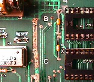
|
-
Replacing the Battery Holder.
The battery holder used on DataEast/Sega games is a bit different than the one used on Williams' games. Instead of attaching at six points on the circuit board, it only attaches at two. But the CPU board is drilled and plated for a six hole battery holder. Because of this, either a Williams or DataEast style battery holder can be used, without any modifications (other than desoldering the four additional holes needed for the Williams style battery holder).
Because the DataEast/Sega CPU board is so flexible, it is recommended to use the Williams battery holder part number A-15814, as used in WPC-S and later Williams games. This battery holder design is much better than the DataEast/Sega (or even earlier Williams) battery holders.
|
An older style Williams batter holder installed in a (slightly corroded) DataEast 520-5003-03 Revision 3 CPU board. Battery polarity orientation is shown. |
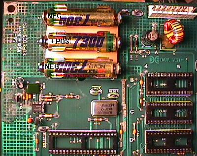
|
-
In either case, whether using a DataEast/Sega or Williams battery holder,
the batteries will regardless mount in the same manner. Unlike Williams
WPC games, the middle battery is mounted "reverse" to the two outside
batteries. That is, the top battery is mounted "NEG POS", the middle battery
"POS NEG", and the bottom battery "NEG POS".
3n. When things don't work: Sound Problems
Sound Board Generations.
There were basically four sound boards used on DataEast games:
The sub-generations of each board type usually denoted different sized EPROMs were used (as games got newer, bigger EPROMs were used). For example, on the 520-5050-01 sound board (Batman, Star Trek, Hook, Lethal Weapon), jumper W6=in and W7=out, which allowed a 27020 to be used at U17 and U21. Then on sound board 520-5050-02 (Star Wars, Rocky&Bull, Jurassic Park), jumper W6=out and W7=in, which allowed a 27040 at U17 and a 27020 at U21. Interestingly, on both boards jumpers W1 to W5 were the same (W1,W4=in; thanks Ray!)
Loud Hum from the Speakers.
The sound works, but there is a very noticible loud hum coming from the
speakers. This is often a ground problem. It could be as simple as
tightening the screws that secure all the printed circuit boards to the
backbox. Also it could mean the large filter capacitor (usually 1000 mfd at 16 volts)
on the sound board needs to be replaced. Look for a large capacitor
that connects +5 volts to ground.
No Sound at All - Sound Board Voltages.
The sound board needs +5 volts, -5 volts, +12 volts, and -12 volts to operate.
These voltages come from the power supply board except for -5 volts,
which is created by the sound board itself.
After the -12 volts gets to the sound board, it is regulated down
to -5 volts using a 7905C voltage regulator at VR1. If the voltage regulator VR1 fails,
this could pass -12 volts directly to chips which are expecting -5 volts,
thus destroying them. This is
a fairly common problem, and will disable the sound board completely.
On games Batman to Batman Forever, the -5 volts goes
to chips U30 and U28 (LM833). On games Laser War to Turtles (sound board
520-5002-0x), the -5 volts
goes to chips 5B (4052), 3B, 6B, 7B (all MC3403).
Check for sound board voltages at the input connector to the sound board. This would be the +5, +12, and -12 volts at connector CN2 (or CN4 on sound board 520-5002-0x used on Laser War to Turtles):
Next check for -5 volts at the capacitor C49. Use a DMM, and put the red lead on the leg of this capacitor which connects to VR1. Put the black lead on the other leg of the capacitor (ground). The DMM should show -5 volts. This applies to all revisions of DataEast/Sega sound boards as used from Laser War to Batman Forever.
On games Batman to Batman Forever (all sound boards but 520-5002-0x), this procedure should be repeated for the +5 volts. This voltage is received directly from the power supply, but it is also produced from the input +12 volts through voltage regulator VR2 (7805C) on the sound board. Check for +5 volts at .1 mfd capacitor C47. Use a DMM, and put the red lead on the leg of C47 which connects to VR2. Put the black lead on the other leg (ground). The DMM should show +5 volts. This applies to all revisions of DataEast/Sega sound boards as used from Batman to Batman Forever.
No Sound at All - PAL Chips.
DataEast/Sega sound boards use specialized PAL program
chips at U19 and U20 (PAL16L8). If there is no sound, and all the
sound voltages are present (+5, -5, +12, -12 volts), suspect these
two PAL chips next. These are custom programmed chips. They can
be ordered from Stern, or custom programmed (email
Jerry Claus
for a quote).
Sound Problems on Checkpoint and Turtles.
Some Checkpoint and Turtles games had their sound boards mis-wired
to the speakers. Make sure the game is wired like this:
3o. When things don't work: Miscellaneous Oddities
Problem: "My game spits out two balls when I start a game. The correct
number of balls are installed. What is the problem?"
Answer: There probably is a broken switch on the ball trough. For example, if you game uses three balls, there will be three ball trough switches. If the third ball trough switch is broken (stuck closed), the game will serve two balls into the shooter lane when a game is started. It does this because when the first ball is served, the third ball trough switch is still (stuck) closed. So a second ball is served into the shooter lane, opening the second ball trough switch, and telling the game it has served a ball and is ready to play. Unfortunately the game's software is not smart enough to check the shooter lane switch to determine there is already a ball served and ready to play!
If the game uses the newer style ball trough with optics, one of the optics is probably not working. There are two sets of optics; the "zero" ball position optic, and the ball jam optic. if either is not working, multiple balls could be served to the shooter lane. Cold solder joints on the optic boards is very common. See the ball trough section for more details.
Problem: My 1992 Star Wars games instantly starts multi-ball mode when a game is started. Balls just keep popping into the shooter lane and then are shot onto the playfield.
Answer: This is an incredibly common problem, and is very confusing. This problem is nearly always cold solder joints on the "L/R" relay, on the PPB board. Because this relay (when not energized) defaults to activating the solenoids, any attempt by the game to light a flash lamp (for example, when a game is started), will instead activate the associated solenoid. The flasher paired with the ball popper is supposed to light, but instead another ball gets placed in the shooter lane. DataEast's auto-ball-fire games all have a 'lightning ball' feature which automatically launches a ball in the shooter lane onto the playfield. This gives the instant multi-ball. To fix this, check the L/R relay (K1) on the PPB board, and resolder the relay's solder joints.
Problem: My Maverick game "hangs" and freezes after each ball drains. It take 10 or 20 seconds for the game to continue.
Answer: I had noted that the machine would occasionally lose the high score table and adjustments I had set. The CMOS RAM chip at 5D was getting power from the batteries, so I presumed that this IC was bad. I also noted that I was not on the latest firmware for the machine So I replaced the CMOS RAM IC, and also upgraded the game ROM to the latest code. With these two changes the game no long "froze" between balls.
Problem: My Last Action Hero (LAH) game will not activate any flash lamps in diagnostic, but instead activates the solenoids. Yet during normal game play, both the flashers and solenoids seem to work fine.
Answer: Check for cold solder joints on the PPB board's select L/R relay. Also make sure the latest CPU ROM software is installed in the game.
Problem: On Tommy, the "blinders" just refuse to work. I have checked voltages, continuity, the smaller driver board, and everything seems OK.
Answer: Remove the J2 connector on the blinder PCB (installed on the left side of the cabinet). As strange as this sounds, this should fix the problem. The blinder PCB is a "shaker motor" board (strange since Tommy does not have a shaker motor).
Problem: Why is there a shaker motor in my Guns N Roses (GnR) game? All other Guns N Roses I have seen have no shaker!
Answer: The first prototype GnR machine did NOT have a shaker motor (however, it did have a drop target in front of the add band member hole). But Japan changed their import rules for games around the time that Tommy went into production. For some odd reason DataEast found that they could avoid a ton of red tape in getting each model approved for import to Japan if there was the same number of motors in every game.
Tommy had three motors - one for each propeller on the airplane and one for the mirror. Thus subsequent Japanese games had to have three motors as well to "match" under this standard. To satisfy this standard (silly as it seemed) the Japanese games had a fan or two added in the backbox (similar to the propeller motors), and one higher voltage motor remained. In WWF it was satisifed by the factory shaker motor, and for GnR DataEast added the shaker to games heading for Japan. But after Sega took control of DataEast, the Japanese motor issues going away for some reason.
So if a GnR has a shaker motor my guess is that the game was originally a Japanese game; either re-imported into the US or converted to some other country at the factory after originally being built for Japan. And the Japanese CPU ROM chip should activate the shaker motor in GnR.
Problem: I need a new motor for my 1992 DataEast Star Wars Death star target. How do I get one?
Answer: Bowman Motors originally made that motor, but they were bought out by Hankscraft Motors in Reedsburg, WI. They can be contacted at www.hankscraft-motors.com. There is a $120 minimum order unfortunately (two motors worth). The motor information needed is on the top of the plate that covers the gearcase part of the motor. For the Death star it says: Model G 24V 3W 6RPM CW 211. The stock motor comes with approx a 1/2" shaft. The shaft that turns the Death Star is 5" X 3/16" and the top 1/4" is threaded for a 6/32" nut (I think an 8/32 would work too). Hankscraft can do different output shafts.

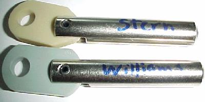
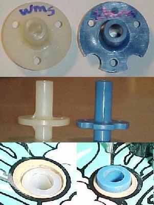

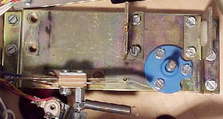
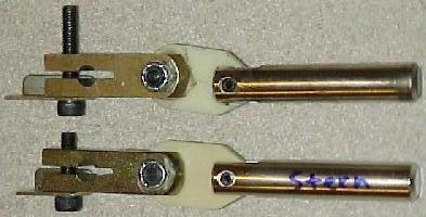

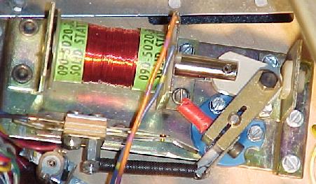
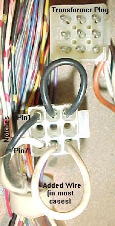 �
�
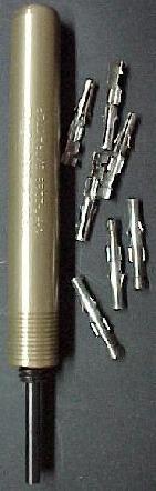 �
�


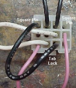
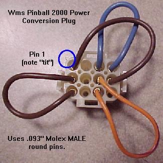