- TIP122: used at Q39-Q46 (multiplexed), Q8-Q13 (special coils), Q23-Q30 (constant power), Q72-Q79 (lamp matrix row returns) on the CPU board. When replacing a TIP122, always replace a TIP122 with a TIP102 instead. The TIP102 is a more robust version of the TIP122. Equivalent transistors for TIP122 = NTE261; TIP102 = NTE2343.
- TIP36c: used at Q1-Q5 on the PPB board (if the game is Laser War or Secret Service, it does not have this board, and hence does not have any TIP36c transistors). These transistors control the high voltage 50 volt coils that were previously controlled by under-the-playfield SMIG relay boards. NTE393 is an equivalent transistor.
- 2N4401: used at Q2-Q7, Q15-Q22, Q31-Q38 on the CPU board. Functions as a pre-driver for the TIP122 transistors. NTE123AP is an equivalent transistor.
- 2N5060: used at Q81-Q88 on the CPU board. Acts as a pre-driver for the TIP122 transistors in the lamp matrix rows (lamp returns). NTE5400 is an equivalent transistor.
- TIP42: used at Q64-Q71 on the CPU board. Controls the lamp matrix columns (lamp drive). The TIP42 strobes the 18 volts for any particular lamp column. NTE197 is an equivalent transistor.
- 2N6427: used at Q56-Q63 on the CPU board. A pre-driver for the TIP42 transistors in the switch matrix columns (switch drive). NTE46 is an equivalent transistor.
- 2N3904: used at Q48-Q55 on the CPU board. Controls the switch matrix columns (switch drive). NTE123AP is an equivalent transistor (which is the same equivalent as the above mentioned 2N4401).
- Turn the game off.
- Put the DMM on ohms (buzz tone).
- Put one lead on the ground strap in the backbox.
- Touch the other lead to the metal tab on transistor Q29.
- If the DMM shows zero ohms (buzz), the transistor is bad! (shorted on). This bad transistor will cause the L/R relay to stay energized.
- TIP122/102: Put the black lead of the DMM on the center lead or on the metal tab of the transistor. Put the red lead of the DMM on each of the two outside legs of the transistor. The DMM should show a reading of .4 to .6 volts. Any other value, and the transistor is bad and will need to be replaced.
- TIP36c: Put the red lead of the DMM on the center lead or on the metal tab of the transistor. Put the black lead of the DMM on each of the two outside legs of the transistor. The DMM should show a reading of .4 to .6 volts. Any other value, and the transistor is bad and will need to be replaced.
- 2N4401 (pre-drivers): Put the red lead of the DMM on the center lead of the transistor (note this transistor doesn't have a metal tab). Put the black lead of the DMM on each of the two outside legs of the transistor. The DMM should show a reading of .4 to .6 volts. Any other value, and the transistor is bad and will need to be replaced.
- TIP42: Put the red lead of the DMM on the center lead or on the metal tab of the transistor. Put the black lead of the DMM on each of the two outside legs of the transistor. The DMM should show a reading of .4 to .6 volts. Any other value, and the transistor is bad and will need to be replaced.
- Press the green button inside the coin door to the "down" position.
- Press the black button once to enter diagnostics.
- Press the black button to move from test to test.
- On games WWF Royal Rumble and later, make sure the coin door is closed while testing coils.
- On games WWF Royal Rumble and later, make sure the coin door is closed (otherwise power will be cut to the coils).
- Check all the fuses. A non-working solenoid could be as easy to fix as just replacing a fuse.
- Find the solenoid in question under the playfield. Make sure the wire hasn't fallen off or become cut from the coil lug (a very common problem).
- Make sure the power wire (the one connecting to the diode's banded side) has not broken "up stream". Power wires are "daisy chained". If a power wire breaks on a previous coil in the chain, no coil "downstream" will have power.
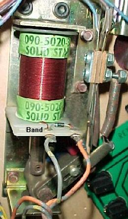
- If the above is correct, make sure the windings of the coil haven't broken off from the solder lugs. If one has broken, it can be resoldered. Make sure to sand the painted enamel insulation from the wire before re-soldering.
- Check the coil diode. For all DataEast/Sega games, the coil diode will be right on the coil, with the banded side of the diode connecting to the power side of the coil.
- First check the fuse! A non-working coil could be as easy to fix as just replacing a fuse.
- Turn the game on and leave it in "attract" mode.
- Lift the playfield.
- On games WWF Royal Rumble and later, close the coin door.
- Put the DMM on DC voltage (100 volts or greater).
- Attach the black lead of the DMM to the grounding strap by the playfield prop rod.
- Touch the red lead of the DMM on either lug of the coil in question.
- The DMM should show a reading of 25 to 80 volts DC. Switch the red test lead to the other lug of the coil, and the same voltage should be shown again. If the correct voltage reading is not shown, no power is getting to the coil. If there is power at only one of the lugs, then you have a broken winding on the coil itself. Replace the coil or fix it (if the winding is an outside winding, you can remove the paper label and unwrap a turn of wire, sand the insulation off, and resolder the coil winding to the lug).
- If no power is getting to the coil at either lug, it may be a coil that is L/R relay selected. Push the green coin door button down, and press the black button. This will put the game in diagnostics mode. This should de-energize the L/R relay, and turn the power to the coil in question on (except for games Time Machine to the Simpsons). If there is still no power (or the game is Time Machine to the Simpsons), use an alligator clip from ground to the metal tab of transistor Q29, to activate the solenoid L/R relay, and retest for power at the coil again.
- A broken L/R relay can cause power to not get to a coil. This will always affect more than one coil. Cold solder joints on the L/R relay to PPB board solder pads can impede power too.
- If no power is getting to the coil, a wire may be broken somewhere. Trace the power wire. Remember, the power wires are "daisy-chained" together. So if there is a break in the wire at a previous coil, the coils downstream will not get power.
- Game is on and in "attract" mode, and the playfield lifted.
- On games WWF Royal Rumble and later, close the coin door.
- Connect an alligator clip to the grounding strap by the playfield prop rod.
- Momentarily touch the other end of the alligator clip to the GROUND lug of the coil in question. This will be the coil lug with the single (thinner) wire attached. The ground coil lug is also the one with the non-banded side of the diode connected. If accidentally the alligator clip is touched to the power side of the coil, the game will reset and/or blow a fuse, as the solenoid high voltage is being shorted directly to ground.
- The coil should fire. If the coil does not fire, it may be a coil that is L/R relay selected. Push the green coin door button into the down position, and press the black button. This will put the game in diagnostics mode. This should de-energize the L/R relay, and turn the power to the coil in question on (if the game is Time Machine to the Simpsons, ground transistor Q29's metal tab to energize the L/R relay, because the coil/flashlamp banks are reversed).
- If the coil still does not fire, either the coil itself is bad, or the coil's fuse is blown causing power to the coil to be absent.
- Game is on, and in diagnostic mode (push the green coin door button down, and press the black button on games Frankenstein and before to go into diagnostics mode).
- Remove the backglass.
- On games WWF Royal Rumble and later, close the coin door.
- Find the transistor that controls the coil and/or flasher in question (refer to the manual).
- Attach an alligator clip to the grounding strap in the bottom of the backbox.
- Momentarily touch the other lead of the alligator clip to the metal tab on the TIP122/102 transistor (only works on these, may damage other transistors).
- The coil or flasher should activate.
- If the coil or flasher does not fire, it may be a transistor that is multiplexed through the L/R relay.
- To energize the L/R relay (which will fire the other coil/flasher that is multiplexed), attach another alligator clip to the grounding strap in the backbox. Connect the other end of the alligator clip to the metal tab of transistor Q29. This will energize the L/R relay on the PPB or MRB board.
- If the coil or flasher does not fire, and the coil or flasher did fire in the previous test, there probably is a wiring problem. A broken wire or bad connection at the connector plug would be most common. It is also possible a driver or pre-driver transistor is bad. Use the DMM meter to test the transistors on the board (see Transistors Testing Procedures for details).
- Remove the backglass.
- Turn the game on, and start a game. Leave the ball in the shooter lane.
- If there is a connector on the CPU board at CN18, remove it.
- Connect an alligator clip jumper wire to the ground strap in the bottom of the backbox.
- Touch the other end of the jumper wire to each pin, 1 to 6, of CPU board connector CN18. Each respective coil should fire (depending on the game, there may be some special solenoids not used, and hence touching a pin or two may do nothing).
- Q38/Q46, Q37/Q45, Q36/Q44, Q35/Q43: The 7408 at 4J, which connects to 5H (74LS273), which connects to PIA 11D (6821).
- Q34/Q42, Q33/Q41, Q32/Q48, Q31/Q39: The 7408 at 3J, which connects to 5H (74LS273), which connects to PIA 11D (6821).
- Q22/Q30, Q21/Q29, Q20/Q28, Q19/Q27: The 7408 at 2J, which connects to PIA 5F (6821).
- Q18/Q26, Q17/Q25, Q16/Q24, Q15/Q23: The 7408 at 1J, which connects to PIA 5F (6821).
- Q2/Q8, Q3/Q9, Q4/Q10, Q5/Q11: special coil (switched solenoid) drivers. Connects to chip 12A (7402). On CPU revision 1 or 2, the logic ends there. On CPU revision 3, chip 12A (7402) connects to chip 11C (7407), and then to PIA 8H or 9B or 11D (6821). On all revisions, resistor network RA24 (4.7k x 8), capacitors C40-C45 (.1 mfd), and diodes D1-D6 (1N5234) are used and can fail (causing the affected coil to lock on).
- Q6/Q12, Q7/Q13: special coil (switched solenoid) drivers. Connects to chip 12B (7402). On CPU revision 1 or 2, the logic ends there. But on CPU revision 3, chip 12B (7402) connects to chip 11C (7407), and then to PIA 11D or 9B (6821). On all revisions, resistor network RA24 (4.7k x 8), capacitors C40-C45 (.1 mfd), and diodes D1-D6 (1N5234) are used, and can fail (causing the affected coil to lock on).
3a. When things don't work: Replacing Components.
-
After finding a bad component, replace it! Transistors,
bridge rectifiers, and most chips are not socketed. They are soldered directly into the
driver board. Care must be taken when replacing a bad component.
See http://marvin3m.com/begin for details on the basic electronics skills and tools needed for replacing circuit board components.
When replacing components, the object is to subject the board to the least amount of heat as possible. Too much heat can lift or crack the board's traces. Too little heat and the plated-through holes can be ripped out when removing the part. ircuit boards are too expensive to replace. So be careful when doing this.
To remove a bad component, just CUT it off of the board, leaving as much of its original lead(s) as possible. Then using needle nose pliers, grab the lead in the board while heating the lead (and not the circuit board!) with the soldering iron. When the solder liquifies, pull the lead out. Clean up the solder left behind with a desoldering tool.
When replacing chips, always install a socket. Buy good quality sockets. A good machine pin socket is desirable. Avoid "Scanbe" sockets at all costs!
When Replacing Bad Driver Transistors...
ALWAYS check the coil mounted diode too! Often the coil mounted diode will break, causing the
driving transitor to fail. If the diode is not replaced also, the driving transistor
will fail again and again. This is often overlooked in DataEast/Sega games.
3b. When things don't work: Locked-On Coils & Flashlamps (Checking/Fixing Transistors and Coils)
If a coil is "stuck on" when the game is turned on, a shorted driver transistor is often the cause. If a coil does not work (and the fuses are good!), an open driver transistor could be the cause. This section will help diagnose this, and other related faults.
What do the Driver Transistors Do?
Basically, a driver transistors completes each coil's path to
ground. There is power at each coil, all the time. The driving
transitor is "turned on" by the game's software, through a TTL (Transistor to
Transistor Logic) chip. When the transistor is turned on, this completes
the coil's power path to ground, energizing the coil.
Driver transistors also work the CPU controlled lamps and flash lamps,
causing a lamp to "lock on".
Sometimes these driver transistors short "on" internally. This completes a coil or flash lamp's power path to ground permanently, making it "stuck on", as soon as the game is turned on. Also a shorted pre-driver transistor, or shorted TTL chip (which controls the transistors) could be the problem (though a shorted driver transistor is the most common cause). To fix this, the defective component (and perhaps some other not defective, but over stressed componets) will need to be replaced.
Driver Transistor Operation.
As described above, the main driver transistor (a TIP122/TIP102 or TIP36) completes
the coil or flash lamp's power path the ground, energizing it. But there are other
components involved too!
Each driver transistor has a "pre-driver" transistor. In the case of a TIP122/TIP102 (the most common driver transistor), this is a smaller 2N4401 transistor.
If the main driver transistor is a TIP36c, this is pre-driven by both a TIP122/TIP102 and a smaller 2N4401 transistor. The bigger TIP36c transistor is an even more robust than the TIP122/TIP102, and controls very high powered, high use coils (like the up kickers).
Then before even the smaller 2N4401 pre-driver transistor, there is a TTL (Transistor to Transistor Logic) 7408/7402 chip. And prior to this is the 6821 PIA (this is really the first link in the chain). This is what in affect turns on the smaller 2N4401 pre-driver transistor, which then turns on the TIP122/TIP102 (which then turns on the TIP36c, if used for the coil/flash lamp in question), and energized the device.
This series of smaller to bigger transistors is done to isolate the hi-powered coil voltage, from the low-power logic (5 volts) on the driver board. Also the 7408/7402 chip and PIA (all operating at +5 volts), which really controls the transistors, can not directly drive a high power TIP122/TIP102 or TIP36c transistor (which is controlling the coil's high voltage by sinking the ground).
If ANY of these components in the chain have failed, a coil/flashlamp can be stuck on, and will energize as soon as the game is powered on!
I have a Stuck-on Coil (or Flashlamp), What should I Replace?
A short summary (before reading all the info below).
The following procedures will test the driver and pre-driver transistors in
question. If either is bad, it will need to be replaced. When replacing either
a driver or pre-driver transistor, replace them both (or in the case of a
TIP36, replace the TIP122/TIP102 and smaller 2N4401 transistor)!
A shorted transistor will cause the other transistors in the link to be
stressed, and they should all be replaced.
Inside the front cover of the game manual is a list of each coil used in the game. Also listed are the driving transistor(s) for each coil. Use this chart to determine which transistors could potentially be bad. Also use the schematics.
If after replacing the driver transistors the coil/flashlamp is still stuck on, then replace the TTL 7402/7408 logic chip. The TTL chip can also go bad. If there is still a problem, the 6821 PIA behind the TTL chip can also fail.
Also remember to test the resistance of a coil after replacing the driver transistors. If a coil gets hot, it can burn the painted enamel insulation off the coil windings. This lowers the overall resistance of the coil because adjacent windings short together. If resistance gets much below 3 ohms, the coil becomes a "short", and will fry its associated driver transistors very quickly!
A Coil just Does Not Work - What is Wrong?
Driver transistors can go "open" too. This means all the logic prior
to the open transistor could be working fine, but the coil will not
energize. If there is power at the coil, this is something to consider
(but first see the test procedures below to make sure the coil itself
is actually OK).
Do the Transistor Test Procedures work 100%?
In short, no. But they do work about 98% of the time, and are an
excellent starting point. But yes, a transistor can test as "good",
but still be bad. The DMM test procedures test the transistors with
no load. Under load, a transistor could not work.
Required Documentation.
When repairing transistors and coils, the game manual will be needed. There are several
sections that are very useful for repair. First is the
page in the "Flash Lamp/Coil Test" section, "Game Diagnostics" chapter
(pictured above in the the Circuit Boards and How They Work section).
The second diagnostic tool is in the "yellow pages" section;
the schematics labeled "Playfield Coil/Flash Lamp Wiring Diagram".
The last schematic is again in the "yellow pages", and is labeled
"Playfield Special Coil Diagram". These tools
show which transistors control which coils/flashlamps. Without this
information, fixing bad coils/transistors is much more difficult.
There are several types of transistors used on the DataEast/Sega CPU and PPB boards:
Coin Door Interlock Switch - IMPORTANT!
Starting with WWF Royal Rumble, DataEast added a coin door
interlock switch. When the coin door is open, this switch opens,
and cuts the +32 volt and +50 volt power directly from the transformer.
DataEast did this for good reason; it helps prevent an accidental
short of the solenoid voltage to a lamp socket, switch lug, or other component.
This prevents possible damage to the CPU board when working under
the playfield with the power on.
When testing coils on games WWF Royal Rumble and later, make sure the coin door is shut. If the door is open, no coils will work in the game!
Interestingly, if while playing a game the coin door opens, and the cabinet flipper button is pressed, the flipper will stay energized! This happens because the 9 volt solidstate flipper hold circuit for the flippers is not interrupted when opening the coin door.
When Replacing Bad Driver Transistors...
ALWAYS check the coil mounted diode too! Often the coil mounted diode will break, causing the
driving transitor to fail. If the diode is not replaced also, the driving transistor
will fail again and again. This is often overlooked in DataEast/Sega games.
The Bank Selected Solenoids.
On all DataEast/Sega games,
transistor Q29 on the CPU board controls the "solenoid L/R select relay" on the PPB board.
This is the relay that controls which bank (either "L" or "R", or sometimes labeled "A" or "B") that transistors Q39-Q46
control. This means one transistor can control two different
devices (usually a flasher on bank R, and a solenoid on bank L).
First Test the Solenoid L/R Select Relay!
When the solenoid A/C select relay is not working correctly,
there can be all kinds of coil problems. A malfunctioning
L/R relay, if stuck on or off, won't give any power
to either the coils or flashlamps. If the relay is constantly energized (stuck on bank "R"),
it's probably because it's driver transistor Q29
is shorted on.
On most DataEast/Sega games, the "L" (or "A") bank was for coils, and the "R" (or "B") bank is for flashlamps. But on games from Time Machine to the Simpsons, this logic was reversed. In these games the "L" bank was used for flashlamps (instead of coils), and the "R" bank was used for coils (instead of flashlamps). Keep this in mind when diagnosing problems.
The first thing to do is to test the solenoid L/R select relay. Turn the game on, and enter diagnostics (entering diagnostics should de-energize the L/R relay; on some games the L/R relay will stay energized after finishing a game because of an after-game flasher light show). Take an alligator test wire and connect it to the metal tab on transistor Q29. Then with the game on and in attract or diagnostic mode, touch the other end of the alligator clip to the ground strap in the backbox (WWF Royal Rumble and later, make sure the coin door is closed). The L/R select relay on the PPB board should click "on and off"; it will click on when the transistor is grounded, and off when not.
If the relay "click" is not heard, do a quick test of transistor Q29 using a DMM:
The Q29 transistor can stay grounded for a period of time. This will not ruin the transistor or the relay. Do not leave Q29 grounded for more than a few minutes. That should be plenty of time to test any coils.
Is the Solenoid L/R Select Relay Bad?
Be aware that relays can go bad too. This can especially
happen if transistor Q29 locks on for an extended time, and leaves power to the
relay turned on. The relay can actually get so hot, it burns the
relay contacts together. Sometimes the solder joints on the L/R select
relay can go "cold" or fatique. This often will make an L/R select relay not work
(but reflowing the relay solder joints can generally fix this).
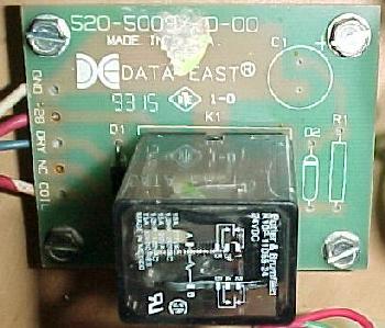
Wrong L/R Relay installed on some TftC Games.
During production of Tales from the Crypt, the wrong L/R select relay on the PPB board
was installed.
This caused solenoids to activate randomly, and flash lamps to not activate at all.
The problem was the PPB's K-1 relay was installed with a 24 volt AC relay, instead
of a 24 volt DC relay. The incorrect AC relay has a relay coil winding of about 2 ohms,
while the correct DC version is about 650 ohms! The lack of ohms will cause the
relay to burn and fail. The relay can be identified easily because it is labeled
"24v AC", while the correct relay is labeled "24v DC" (or the relay's winding
can be measured with a DMM). Games with serial number
101664 or later have been inspected for this problem. If this 24 volt AC relay is
installed, replace it with the correct 24 volt DC relay. This was mentioned in
service bulletin number 52.
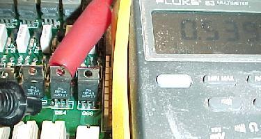
|
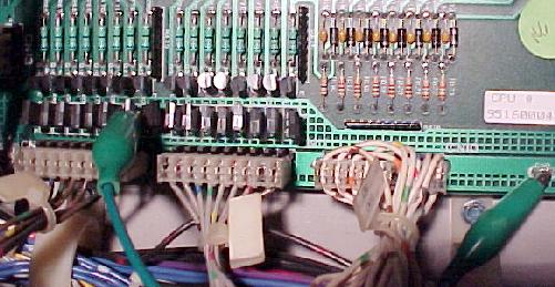
Turning on Relay L/R to test both coils/flashers that driver transistors Q39-Q46 control. Here transistor Q29's metal tab is grounded with an alligator clip. Note there is a ground test point on the CPU board to the right of connector CN10. |
|
Transistor Testing procedures, circuit board out of the game.
If a circuit board is out of the game for some reason,
test all the solenoid/flasher driver transistors. It only
takes a moment, and will ultimately save time.
To test a transistor, set the digital multi-meter (DMM) to the "diode" position.
|
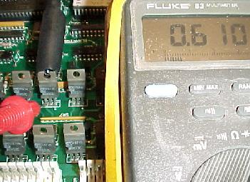
Testing a TIP122/102 transistor on the CPU board. |
|
|
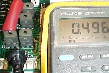
Testing a TIP36c on the PPB board. |
|
|
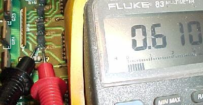
Testing a 2N4401 pre-driver on the CPU board. |
|
|
Testing a TIP42 lamp matrix column driver transistor on the CPU board. |
|
Most often transistors short when they fail. This will usually give a reading of zero or near zero, instead of .4 to .6 volts.
|
For games with "Easy A-Just", enter the diagnostics with the green button in the "down" position. Then press the black button. If the green button is "up", the audits/adjustment menu will be shown instead. |
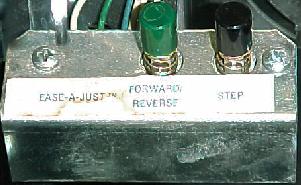
|
-
Testing Transistors/Coils, circuit boards installed in a (near) WORKING game,
using the Diagnostics Test.
If the game powers on, the diagnostics can be used to test most devices. On games Frankenstein and before, from the attract mode:
-
Solenoid Doesn't Work during Diagnostic Tests.
If a solenoid doesn't work from the diagnostic tests, here's what to check. Turn the game off before doing this.
A Coil Doesn't Work, What To Do.
The following procedures will start at the coil, and work back
to the CPU board, testing components in order. This will eliminate heathly components
and make finding the problem easier.
Testing for Power at the Coil.
Most pinball games (including DataEast/Sega) have power at
each and every coil at all times. To activate
a coil, GROUND is turned on momentarily by the driving transistor
to complete the power path. Since only ground (and not power) is turned on and
off, the driving transistors have less stress on them. With this in
mind, if a coil is artificially attached to ground, it will fire
(assuming the game is turned on and in attract mode). This procedure
tests for power at the coils (does not work for flipper coils):
Coil Test to Make sure the Coil is Good.
Here's another method of testing coils, which is more "low-level".
This will test if the coil itself is good, and that there is power
at the coil.
Testing TIP122/102 Transistor and Down-Stream Wiring/Coil.
If the coil fires in the above test, there may be a transistor problem.
Next test the TIP122/102 transistors. Only
do this for the TIP122 or TIP102 transistors! Damage can occur if this
test is done on other transistors (like TIP42 or TIP36). This test
will test everything from the CPU board down to the coil itself. If
the TIP122/102 and coil pass this test, and the coil still doesn't
work in game play, the problem is more "up stream". All that is
left is the 2N4401 pre-driver transistor, and the logic TTL chip
that ultimately controls the whole process (a 7402 for the special
coils or 7408 for the constant power solenoids), and the PIA 6821 chip.
Note the TIP36c transistors can be indirectly tested using this method too, BUT the TIP122 pre-driver must be grounded. All TIP36c transistors use a TIP122/TIP102 as a pre-driver. If the metal tab on the pre-drive TIP122/TIP102 is grounded, this will activate the TIP36c, which will energize it's associated coil.
"Special Coil" Problems (Trickiness on CPU Revision 3 Games).
Before CPU board Revision 3, the six special coils were not CPU controlled.
Instead simple circuitry was used to sense and turn on the special coils. With the introduction
of CPU Revision 3 (Back to the Future and later), the special coils became CPU
controlled ("non-reflexive" circuitry). However to keep the CPU boards backwards compatible,
the old special coil circuit was left intact on the Revision 3 CPU boards (even
though Revision 3 games did not use it).
On games Back to the Future and later, there is a potential problem with this backwards compatibility. The old special coil circuitry can be damaged, and cause the special coils to lock on. This can be very frustrating. For example, say a pop bumper coil locks on immediately when the game is powered on. After replacing its associated TIP122 transistor and the 2N4401 pre-driver transistor, and checking the coil's diode, the coil is still locked on! So go back a step further, and replace the 7402 chip at location 12A or 12B. And still the coil is locked on. Finally go all the way back, and replace the 6821 PIA chip at location 8H or 9B. Yet still the coil is locked on!
The problem could be in the parallel, but unused, old special coil circuit! If just one of the small capacitors at locations C40 to C45 (.1 mfd) shorts, its associated coil can lock on. This is a very common, but confusing problem. Also, one of the diodes at locations D1 to D6 (1N5234), or the resistor pack at R24 (4.7k x 8) can short (less likely, but still worth checking). In CPU Revision 3 games, these components are unused, but they can still become damaged!
It is easy to determine which circuit a game is using. If connector CN18 (upper right hand corner as facing the CPU board) has a plug connector attached, the game is using the older special coil circuit. No connector at location CN18 means the game is a ("non-reflexive") CPU Revision 3 or later machine.
Testing the Special Coil Circuit.
The old special coil circuit can be easily tested. This procedure
works for all CPU boards from Revision 1 to Revision 3.
Testing the under-the-playfield Relay Boards.
On most DataEast/Sega games, there are a mix of some 50 volt
and 25 volt coils. For games without a PPB board (Laser War, Secret Service),
there is a SMIG relay board to power the 50 volt coils. A TIP122/102
transistor on the CPU board energizes the under the playfield
relay on this board. This relay then turns on the ground to the 50 volt
coil, motor or other device. This was done because the original TIP122 on the CPU
board couldn't handle the current draw of motors or 50 volt coils.
The under the playfield SMIG relay boards were no longer required for 50 volt coils on games with a PPB board. That's because the PPB board had TIP36c transistors to control the 50 volt coils, replacing the small SMIG relay boards.
Many newer DataEast/Sega games still use under-the-playfield relay boards. Sometimes they are used to turn off and on sections of the playfield GI lamps. They are also used to power motors.
It is easy to test the under the playfield relay boards. Connect an alligator clip wire to the "DRV" lead on the small relay board (on games WWF Royal Rumble and later, close the coin door). Connect the other end of the alligator clip to ground (grounding strap by the playfield prop rod). This will energize the relay (a "click" should be heard), and the device it powers should also operate. If this is a GI relay, the connecting GI playfield lighting string should turn off.
|
Grounding the "DRV" lead (blue wire, second from bottom) with an alligator clip will energize the device this board controls. In this case (Jurassic Park), this relay turns on and off a string of playfield GI lamps. |
|
-
Cold, Fatiqued or Cracked Solder Joints on the Relay Boards.
Quite often the solder joints on the under the playfield relay boards are cracked or "cold". If there is a problem with any device that is controlled by a relay board, re-solder all the solder points on the relay board. This is a very common problem!
I've Done the Above Tests & they Work, but the Coil still doesn't
work in Game mode.
After performing all the above tests and replacing/testing the coil, TIP36c (if used),
TIP122/102 and/or the 2N4401 transistors, the coil still doesn't work in game mode!
Now there are the logic components that need to be tested or replaced.
Here is breakdown of what logic chips control the following TIP122/2N4401 transistor
pairs:
|
Turning on Relay L/R to test both coils/flashers that driver transistors Q39-Q46 control. Transistor Q29's metal tab is grounded with an alligator clip. |
|
|
Installing a New Transistor.
After determining a coil transistor is bad,
there are a few things to keep in mind. Most TIP122/102 transistors
also have a "pre-driver" transistor (2N4401 or NTE123AP).
When replacing a coil's TIP122/102 transistor, it's a good idea to also replace its corresponding pre-driver. It will be located near the TIP transistor. See the schematics to determine the specific pre-driver transistor(s).
Games with a PPB board use a bigger TIP36c driver transistor for high voltage devices. These TIP36c transistors have TWO pre-drivers: a TIP122/102 and a 2N4401 transistor. Again, if the TIP36c has failed, it's a good idea to replace both corresponding pre-driver transistors.
Replacing the pre-driver transistors is optional (if they test OK). These pre-drivers can be tested instead of just replacing them. However if the driver transistor has failed, the pre-driver was probably over-stressed too. It is just a smart idea to replace the pre-driver transistor(s) too.
Replace TIP122 transistors with TIP102?
This is a very common question. The TIP102 is a more "hardy" transistor
than the TIP122, yet works exactly the same. So why not replace a bad
TIP122 with a TIP102? Some people
would argue against this, claiming the TIP102 will not go bad as quickly,
and therefore can cause more heat and damage the circuit board before or
while it fails. But if either type transistor is already shorted, it really doesn't
matter if it's a TIP122 or TIP102. It's still shorted, and it will still cause
the same heat damage. My recommendation is to
replace all bad TIP122 transistors with the more robust TIP102.
|
The diode mounted right on the coil, Note the two thicker red power wires go to the banded (power) side of the diode. The single thinner wire goes to ground. |
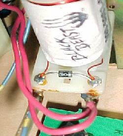
|
-
When Replacing Bad Driver Transistors... (a repeat warning!)
ALWAYS check the coil mounted diode too! Often the coil mounted diode will break, causing the driving transitor to fail. If the diode is not replaced also, the driving transistor will fail again and again. This is often overlooked in DataEast/Sega games.
Coil Diodes.
On all DataEast/Sega pinball games, each and every
coil must have a coil diode.
This diode is VERY important. When a coil is energized, it
produces a magnetic field. As the coil's magnetic field
collapses (when the power shuts off to the coil),
a surge of power as much as twice the energizing voltage
spikes backwards through the coil. The coil diode prevents
this surge from going back to the circuit board and damaging components,
or causing the CPU to get confused (which often results in a game
reboot or strange scoring behavior).
If the coil diode is bad or missing, it can cause several problems. If the diode is shorted on, coil fuse(s) will blow. If the diode is open or missing, strange game play will result (because the CPU board is trying to absorb the return voltage from the coil's magnetic field collapsing). At worst a missing or open diode can cause the driver transistor or other components to fail.
-
When Replacing a Coil Diode...
Remember to always install a coil diode with the banded end of the diode to the power wire coil lug! The power lug is the one with the thicker red or purple wire(s) connected to it. This is usually the lug with TWO wires connected to it (because the power wires "daisy chain" from coil to coil). If a diode is installed in reverse, it will instantly short and be ruined when power is applied (and often blow a fuse, and sometimes kill the coil's driving transistor!).
- On games WWF Royal Rumble and later, make sure the coin door is closed!
- Have the power wires fallen off the coil's solder lugs?
- Is the coil damaged? Has the internal winding broken off the coil's solder lug?
- Is there power at the coil? See Testing for Power at the Coil for more details.
- If there is no power at the coil, check its fuse.
- Check the other coils that share one of the same wire colors. Are they working too? If not, suspect the fuse that handles these coils.
- Power to coils are often ganged together. If the power wire for this coil has fallen off a previous coil in the link, power may not get to this coil.
- Using the DMM and the continuity test, make sure the coil connects to the correct connector/pins on the CPU board.
- Check the driving transistor. Usually this transistor will short on when it fails, but not always.
|
The coil diode as used on a flipper coil, Robocop and later. This lower flipper coil is on Jurassic Park, and hence has an EOS switch. |
|
-
Test a Diode on a Coil?
Coil diodes can be tested. They do fail and they do break. This is true mostly for just the coil diodes that are actually mounted on the coil itself. Testing coil diodes is somewhat a waste of time. If a coil diode is suspected bad, just cut the old one off and solder a new one on. Diodes are so inexpensive, it's not really worth trying to test them. Most bad coil diodes are physically broken, and the damage can usually be seen.
If the coil diode is mounted on the coil (which it should be!), clip one end of the diode off the coil lug to test it (that's why just replacing the diode is a good idea if a problem is suspected).
Use the DMM set to "diode" setting. With the black lead on the banded side of the diode and the red lead on the non-banded side, the DMM should show between .4 and .6 volts. Reverse the leads (red lead to banded side of diode and black lead to non-banded side), and it should show a null reading. If these readings are not shown, replace the diode with a new 1N4004 diode. Don't forget to resolder the cut diode lead if the diode is not replaced.
Test the Coil Resistance with a DMM.
After replacing the driver transistor, ALWAYS measure the resistance
of the associated coil. This is important.
If a coil gets hot (becuase its driver transistor was shorted),
it can burn the painted
enamel insulation off the coil windings. This lowers the overall resistance
of the coil because adjacent windings short together.
If resistance gets much below 3 ohms, the coil becomes
a "short", and will fry its associated driver transistors very quickly!
Installing a New Coil.
Many replacement coils will come with a diode soldered across
its solder lugs. All coils should have a diode mounted on them.
Remember to install the coil wires correctly!
The coil's ground wire (usually the smaller wire) MUST go to the
lug of the coil with the non-banded side of the diode. The power wire
connects to the lug with the banded side of the diode. If
the wires are reversed, this essentially causes a shorted diode,
which destroys the diode and sometimes the driving transistor.
Check nearby coils for reference. Remember
the power wires are usually "daisy chained" together. So the power
lug of the coil is the one with two wires connected to it.
Coil Doesn't Work Check List.
If a coil doesn't work in a game, below is a check list to
help determine the problem.
Before starting, is the coil stuck on? (Hint: is there heat, smoke and a bad
smell?). If so, the coil's driving transistor has probably failed.
Turn the game off and check the driving
transistor, and replace if needed. See Transistors
Testing Procedures for more info.
If the coil just doesn't work, here's a list of things to check:
Flippers don't work, and Neither do the Special Coils.
The flippers do not work during game play, and all
or some of the special coils (pop bumpers, slingshots) do not
work either. If the fuses are Ok, check the chips at locations
12B and 12A (7402). Often the chip at 12B will fail, causing
the flippers and the special coils to not work. The chip at
12B is also used to enable "blanking". If this chip has failed,
often the CPU will not even boot properely.
Problems with Transistor Q54 on Monday Night Football.
DataEast issued service bulletin number 22 regarding the problem of
transistor Q54 failing. This is caused by the outhole kicker coil
(under the metal lower ball arch) getting a short between
one of the coil lugs and the coil stop. This shorts 32 volts to the
switch matrix, which eventually causes transistor Q54 to fail.
To fix this, remove the lower ball arch. Inspect the outhole kicker's
coil stop. Put a piece of electrical tape between the coil's lugs
and the coil stop to prevent this electrical short.
3c. When things don't work: Game Resets (Diodes, Filter Caps, Bridge Rectifiers, Power Supply) and Strange Game Behavior.
-
A very common problem with DataEast/Sega games is random game lock-ups. This can happen
any time, but seems most prevelant during hard game play (like multiball). The game
just locks, no scoring, displays are frozen, lamps locked in their last state.
Another very confusing problem can be just strange game behavior. Solenoids can
fire that were not switched, or strange game features and scoring occur.
Broken Coil Diodes.
The most common cause of these problems is a broken diode on the coil(s).
If a diode breaks (or fails) on a coil, this allows a demagnetizing spike to
go back to the CPU board. As a DC coil's electromagnetic field collapses when it is de-energized, it creates
a spike that travels backwards. The purpose of the diode(s) on a coil is to
stop this spike from going back to the CPU. The constant jarring of a
coil can cause the diode to break or crack.
The most common coil diodes to break are located on the flipper coils. The pop bumper and slingshot coils also can break their diodes.
On coils other than the flipper coils, a broken coil diode often causes the coil's driving transistor to short. If this happens, the coil will stay "locked on" as soon as the game is turned on. If the transistor is replaced on the CPU board, and the coil diode is not also replaced, the transistor will short again. This is a very commonly overlooked problem!
Random game lock up can happen if a flipper coil's diode breaks or fails. This is noticed the most during multiball play, because the flippers are used the most during multiball. The best solution is just to replace every flipper coil diode. These 1N4004 diodes are very cheap and easy to replace. It only takes a few minutes to cut the old ones off and replace them with new 1N4004 (or 1N4007) diodes. Testing these diodes really is a waste of time, as they are so cheap (and can often test as good when they are really bad).
The Diode's Band: Install them Right.
Remember when replacing coil diodes the new diode MUST be installed
with the band in the same direction as the removed diode (assuming
it was installed correctly, which isn't always a good thing to assume).
The diode's band is always connected to the power lug of
a coil. If a diode is installed in reverse, that is the equivalent
to having no diode installed! Note diode installation is slightly more complicated
to figure out on three lug flipper coils. On two lug coils, the power lug is usually the thicker
of the two wires. Check the schematics if unsure.
|
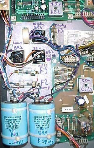
The backbox bridges, filter capacitors, and fuses, as used on a large 192x64 dot matrix games. The two filter caps are used for BR1 (CPU controlled lamps) and BR3 (score display, only present on games with the large 192x64 DMD). BR2 is used for +32 volt solenoids, and hence does not need a filter capacitor. The game pictured here is Baywatch. All other DataEast/Sega games without the 192x64 score display will be lacking BR3, the second large capacitor, and fuse F3. |
|
- CN1 pin 1: 18 volts from bridge BR1. This goes directly to power supply connector CN4 pins 5,6,7,8 for the lamp matrix. On games Checkpoint to Guns N Roses, this also supplies voltage to the power supply's voltage regulator VR1 which creates +12 volts for the DMD, going to CN5 pin 5 (for games with 128x16 and 128x32 dot matrix displays only).
- CN1 pin 2: 32 volts from bridge BR2 for the solenoids.
- CN1 pin 3: 32 volts from bridge BR2 for the solenoids.
- CN1 pin 4: High voltage for the displays (games with alpha-numeric and 128x32 displays only).
- CN1 pin 5: Not used.
- CN1 pin 6: Goes directly to power supply connector CN3 pins 1,2.
- CN1 pin 7: High voltage for dot matrix display (unused on pre-dot matrix display games).
- CN1 pin 8: Not used.
- CN1 pin 9: High voltage for dot matrix display (ground on pre-dot matrix display games.
- CN1 pin 10: 9 volts AC to power supply bridge DB1 for generating +5 volts logic. It is also used to generate the +12/-12 volts for the sound board, by doubling up with pin 11's 9 volts (to get 18 volts).
- CN1 pin 11: 9 volts AC to power supply bridge DB1 for generating +5 volts logic. It is also used to generate the +12/-12 volts for the sound board, by doubling up with pin 10's 9 volts (to get 18 volts).
- CN1 pin 12: Ground for pins 10,11.
- PIA (Peripheral Interface Adaptor) and +5 volt LED turns on immediately.
- After about 1/2 second, the PIA LED turns off.
- Blanking LED turns on next.
- +5 volt and Blanking LEDs will stay on (until the game is turned off).
- PIA LED turns ON (and stays on), blanking LED never turns on: EPROM at location 5C and/or 5B is bad.
- PIA LED turns ON, turns OFF (and stays off), blanking LED never turns on: EPROM at location 5C and/or 5B is bad (this LED sequence is very rare).
- PIA LED turns ON, turns OFF, then turns ON (and stays on), and blanking LED never turns on: 6264 RAM at location 5D is bad.
-
DB1 Power Supply Bridge Rectifier Problems.
The power supply board's DB1 bridge rectifier supplies +5 volt and +12 volts to the entire game. This bridge can fatiqued and cause the game to have random resets. Often the power supply's solder points for this bridge are cracked (or even have black rings around the bridge leads, caused by voltage arcing across the crack). The bridge should be replaced with a new one (35 amps, 200 volts or higher).
|
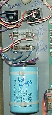
The backbox bridges, filter capacitor, and fuses, as used on all games up to Guns N Roses. The one filter cap is used for the CPU controlled lamps. The game pictured here is Tommy. |
|
-
Replacement Bridges and Diodes.
All the stock bridges installed in DataEast/Sega games are 35 amps 200 volts with lug (not wire) terminals. The original part number will be something like "MB3502" or "MB352" (signifying 35 amps at 200 volts). A replacement bridge can be any voltage or amp value at that rating, or higher. Since the cost is usually no different, buy 35 amps 400 volt replacement bridges with lug terminals. These are available from Competivitive Products Corp (800-562-7283). Radio Shack even sells 35 amp bridges at 50 volts (which isn't enough voltage). But if you look at the bridge inside the Radio Shack package, often then are labeled 3502 or 352 (35 amps 200 volts), and not 50 volts. Always buy only the labeled bridges from Radio Shack. Sometimes these "35 amp" bridges are labeled 1001W (10 amp 100 volts!). Obviously put that one back and grab another!
+5 volt Filter Capacitor(s).
The +5 volt logic filter capacitor on the power supply board is
very important. This keeps the +5 volts smooth and steady. If
this capacitor fails, the +5 volts can become rough, and cause
the CPU to reset during game play. This can often be seen
during game play, when both flipper buttons are pressed, or during
multiball when a lot of coils are firing simultaneously.
Power supplies #520-5047-00, #520-5047-01, #520-5047-02 (Laser War to Guns N Roses) used a single 18,000 mfd 25 volt capacitor at C4 to filter the +5 volts logic. When DataEast/Sega switched to the super-sized 192x64 dot matrix display, the power supply changed to #520-5047-03. This newer version switched from a single 18,000 mfd filter capacitor, to four 4700 mfd 25 volt caps at C11 to C14 (for a total of 18,800 mfd). This was done for reliability reasons. If one of the capacitors failed, the other three could probably still filter the +5 volts enough to keep the game running.
|
DataEast power supply #520-5047-00 (small DMD game). DB1 is the square gray metal "block", right middle of this picture. |

|
-
For additional reliability on games Laser War to Guns N Roses,
it is a good idea to solder an
18 gauge wire from the "+" lead of bridge DB1 to the "+" lead
of capacitor C4. Solder another 18 gauge wire from the "-" lead of the
bridge DB1 (the lead diagonal to the bridge's "+" lead) to the "-" lead of capacitor
C1. These added wires will help prevent future problems with cracked solder joints on
the power supply board components.
The same treatment can also be done on the four games that use power supply #520-5047-03 (Maverick, Frankenstein, Baywatch, Batman Forever). But instead solder the 18 gauge wire from the "+" lead of bridge DB1 to the four "+" leads of capacitors C11 to C14 (daisy chain the wire). Solder another 18 gauge wire from the "-" lead of the bridge DB1 (the lead diagonal to the bridge's "+" lead) to the "-" lead of capacitors C11 to C14. This is a less important modification on this power supply, but is still a good idea.
Power Supply Connectors CN1 and CN2.
On the power supply there are two "square" connectors (opposed to the
inline connectors). Connector CN1 provides incoming power to the power
supply board. Connector CN2 is a centralized ground plug. If either
of these connectors have cracked or cold solder joints on the power supply
board, random game resets can occur. Check these connectors for cracked or
burnt pins on both the power supply board, and the connector plug.
|
The large square connector is CN1. Notice the burn mark on the plastic housing on the top right side (pin 10,11,12), which supply 9 vAC to the power supply to create +5 volts logic and +12/-12 volts (for the sound board). |
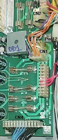
|
-
Here are the pinouts for the main power connector CN1 (power supply generation differences
are listed). Pins 1,2,3
are the pins surrounded by the "notches" on the sides of the connector plug.
Warning about Power Supply connector CN4.
On all DataEast/Sega power supply revisions, connector CN4 directs
18 volts (CPU controlled lamps) and 32 volts (solenoids) to the game. This connector is
twelve pins, and has NO key pin. If connector CN4
is removed, it is very easy to replace the connector
housing shifted one pin to the right or left! This will immediately blow
either the 18 volt lamp fuse or 32 volt solenoid fuse, which are
both bolted to the rear of the backbox.
Random Game Resets On JP, LAH and TftC.
During game play, the games Jurassic Park, Last Action Hero and Tales
from the Crypt randomly reset.
This occurs beacuse the +5 volt line is shorting against the ground backbox metal
plate. This grounding plate lies behind all of the printed circuit boards mounted
inside the backbox. The metal plate can bow, causing it to intermittently short
against one of the backbox circuit boards. This will cause the game to reset.
To fix this problem, remove all the circuit boards (label the connectors!),
and remount the metal backbox grounding plate to remove the bow. Another
solution is to remove the sound board and affix an insulting material to
the metal plate directly behind the sound board at connector CN2. This will
insulate the metal grounding plate from the sound board (which is the board
most affected by this bowing metal plate). Make sure the insulating material
is non-conductive, and thick enough so it cannot be perforated.
This problem was discussed in service bulletin number 55.
Jurassic Park's Coils Fire at Random.
One of the main playfield wire harness trunks in JP can rub against the
upper right flipper coil stop. The vibration of the flipper coil can
cause the harness to "saw" against the coil stop, shorting the wire(s).
This can cause random coil firing, blown fuses, and switch matrix
shorts. To fix this, first inspect the wires for any cuts or shorts.
Then resecure the wiring harness with nylon wire ties. Use
the ties to pull the wiring harness away from the coil stop.
This problem was discussed in service bulletin number 53.
View this bulletin by clicking
here and
here.
Hook Erratic Slam Tilt Problems.
Intermittently Hook performs strangely, and occassionally "slam tilts"
or kicks solenoids for no apparent reason. This can be caused by an
intermittently grounded switch strobe line. Most often, this is caused
by the green wire with the yellow trace on the left drop target bank.
This wire gets pinched against the playfield support bracket. To fix this,
check this wire on the drop target, and make sure it is not pinched
by the support bracket. Dress the wire with electrical tape or
heat shrink tubbing, and a tie wrap, to prevent future occurances.
This problem was discussed in service bulletin number 37.
Power Supply Missing +5 volts.
If +5 volts is missing on the power supply, the obvious culprits are IC1 (a MC1723 chip) and
transistor TR5 (2N6057). These essentially regulate the +5 volts. But before replacing these,
check the surrounding capacitors. This includes C2 (100mfd 25v), C3 (47mfd 25v),
C5 (470p 50v), C6 (.1mfd 50v), and C7 (330mfd 25v).
3d. When things don't work: Power-On CPU LEDs and Sounds
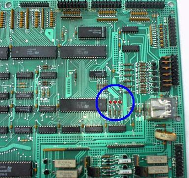
CPU Power-On LEDs.
At power-on, the CPU board performs several self tests. While watching the LEDs (Light Emitting Diode)
on the CPU board, some information can be derived from them.
If all the self tests pass, the LEDs illuminate in the following order at power-on.
|
The three LEDs on the CPU board. |
|
|
The LEDs when the game is booted and running; the blanking and +5 LEDs are on. |
|
-
If there is a problem with the CPU when the game is turned on,
the PIA LED will usually stay on, and not turn off
(and the Blanking LED will not turn on).
Here is what this means:
To get any more information from the LEDs, use the CPU Test EPROM (which is discussed in the section, CPU Diagnostic Test EPROM).
Power-On Score Display Messages.
When turning on a DataEast/Sega game (Checkpoint or later)
with a dot matrix display, almost immediately the
Display EPROM version should be shown in the
score display. This happens because the dot matrix controller
board has its own Z80A (Checkpoint to Hook with a 128x16 display) or
68B09 (Lethal Weapon to Guns N Roses with a 128x32 display)
or 68000 (Maverick to Batman Forever with a 192x64 display) CPU chip.
The dot matrix controller board will complete its boot-up first,
and hence the EPROM display version message is shown first,
before the CPU board can show its CPU EPROM version number.
The dot matrix controller CPU is used only to display the dot matrix
animations on the score display.
This is in addition to the 6808 (or 6802) CPU chip on the CPU board itself (which is
used to control the lamps, solenoids, switches, game rules, etc.).
After a couple seconds (or after the display EPROM version message, Checkpoint and later), the CPU EPROM version (and often country) will be displayed. The only exception is games with no display EPROM (Simpsons and before without a dot matrix control board). On these games just the CPU EPROM version will be displayed (since there is no display controller board and no separate display CPU).
The Display EPROM version shows, but then the Game Stops booting.
This happens on games Checkpoint and later with a dot matrix display. The dot
matrix controller board, with its own separate CPU, boots-up fine. Then the
game's main CPU board does not boot, so the game freezes.
Check the power-on LED flashes to see if they
give any information as to the cause (also see the section below
titled Fixing a Dead CPU).
Power-On Sounds.
As soon as the power is turned on,
the game should play a short word or music phrase.
The phrase will be short, just one or two seconds long,
and it may not be a complete phrase. This is part of
the normal power-on sequence.
3e. When things don't work: DataEast's CPU Diagnostic Test EPROM.
-
DataEast/Sega has a diagnostic test CPU ROM available for all
DataEast/Sega pinball CPU boards from Laser War ("version 1") to
Batman Forever ("version 3b"). This
provides more indepth diagonstics for their system,
because the flash codes available with the game EPROM really do not give
much diagnostic information.
The diagnostic test EPROM will need to be burned into an EPROM though. The DataEast test 27512 ROM image for position 5C is available here.
CPU Jumpers.
Early DataEast games (Laser War to Batman) may require the CPU board
to be rejumpered to use a 27512 EPROM at position 5C.
The two jumpers used in all DataEast/Sega games are J4 and J5. These two jumpers
dictate the maximum size of the CPU EPROM at position 5C. Games Secret Service to Batman
were released with a 27256 EPROM as the largest EPROM usable at position 5C, and
jumper J4 installed and jumber J5 removed. Star Trek 25th Anniversary
to Batman Forever were released with a 27512 EPROM as the largest EPROM
usable at position 5C, and jumper J5 installed and jumper J4 removed.
Use jumper J5 installed and J4 removed when utilizing
the diagnostic test 27512 EPROM at position 5C. Jumpers are discussed
in the section titled Getting Started: Different Board Generations,
CPU Jumpers.
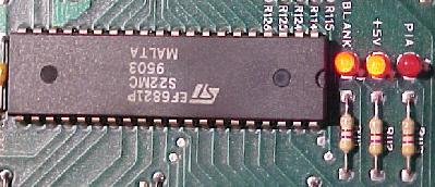
|
The PIA LED on the right will flash up to eight times with the diagnostic test EPROM installed. The flashes indicate what CPU board component is being tested. |
|
|
-
Diagnostic Test EPROM Usage.
With the power off, replace the current CPU ROM chip at position 5C with this diagnostic 27512 EPROM. If your game is Laser War to Batman, the CPU board will have to be rejumpered to use a single 27512 EPROM at position 5C. Note the three LED lights in the center right of the board. The far right most LED (labeled "PIA") will flash as the game powers up with the diagnostic EPROM installed.
Note there is a long pause after flash one only. Often the diagostic chip will flash the PIA LED eight times and turn off, briefly flash the Blanking LED, and then repeat the sequence of eight PIA LED flashes. The reason for the second set of eight PIA LED flashes are unknown. After successfully completing all the flash sequences, the CPU board's RY1 flipper enable relay will click on. Then all coil/flashlamp devices will pulse on, one at a time, in succession.
The Six Special Coils.
The six special coils are NOT tested
by diagnostic EPROM! The reason for this is simple; on CPU board
revisions 1 and 2, the six special coils are not CPU controllable.
Therefore to make the dianostic test EPROM work in these early CPU boards,
the six special solenoids are not tested by the diagostic test EPROM.
How to Count Flashes.
When the CPU board is initially powered on with the diagnostic test
EPROM, the PIA LED will immediately turn on. This is considered the
first "flash" (many people think the first darkening of the LED is
the first flash, but this would mean there was only a total of seven flashes,
not eight). Just keep this in mind when referring to the flash
codes listed below.
The completion of a flash means the associated chip has passed the diagnostic test. For example, if the LED turns on and stays on (never turns off), this is considered the first flash (and hence, the EPROM at 5C is faulty). If the LED turns off four times then stays lit (the fifth flash), chip 11D would be bad.
DataEast Test EPROM instructions, as written by DataEast.
The test ROM for DataEast CPU boards has the following
functions. When the Test ROM is installed into a CPU board
and power applied, the CPU will perform power-up self tests
and then immediately go into burn-in cycles with no
intervention. It is not required that the Test button be
pressed in order to initiate burn-in cycles.
The power up self-test will check major components on the CPU board and flash the LED as each one appears normal. If any fail, the LED will stay on. The tests consist of a checksum test of the ROM and read/write test of the RAM and the PIA's. The PIA test will NOT check both sides of all PIA's since certain PIA ports are designed to be inputs and the loading on those ports will determine the data seen by the CPU. However, those ports designed to be outputs will be written to and read from in order that basic go/no-go functionality can be checked.
Flash  Position  Item Tested
-----  --------  -----------
  1    5C/5B     EPROM checksum error
  2    5D        RAM read/write error
  3    5F        PIA1 solenoid read/write $2100
  4    8H        PIA5 switch read/write $3002
  5    11D       PIA2 lamp read/write $2402
  6    11B       PIA3 display2 read/write $2802
  7    9B        PIA4 display1 read/write $2C02
  8    7B        PIA6 sound read/write $3402
The burn-in test will cycle through the solenoids, lamps, display and sounds like the present burn-in, with the following exceptions.
- The solenoid cycling will go through all the solenoid matrix positions.
- The lamps will go through all the patterns of rows and columns, as well as individual lamps; any shorts or opens will be easily seen on a test set lamp matrix board [DataEast is referring to a test fixture lamp matrix board that has 64 lamps, one for each row and column].
- If any matrix switches become closed, the lamp patterns will stop for a time. The lamp(s) corresponding to the matrix position of any closed switch(es) will be turned on. This faciliates testing of the switch matrix. A short time after the switch matrix becomes clear the lamps will go back to patterns. This also means that if any switch matrix position appears closed on power-up, the corresponding lamps will be turned on after the power-on self tests for a visual indication of where problems are located.
Written by Neil Falconer, DataEast, 1/6/93
3f. When things don't work: CPU and Display EPROM versions.
-
DataEast/Sega games often have many versions of the (CPU and display) EPROMs
(Erasable Programable Read Only Memory).
It is important to run the latest available versions of both. The CPU EPROMs
are the game's main programming. This includes the rules for the game, and
control of all the electronic devices and coils. The latest version is very important
on some games. For example, on Jurassic Park, the CPU EPROM code version 5.10 was
changed so the T-Rex motor was pulsed, saving the motor and gearbox from undue wear.
- A = English Language
- G = German Language
- F = French Language
- S = Spanish Language
- I = Italian Language
The display EPROMs (games Checkpoint and later) hold all the graphics and text needed for display on the dot matrix score display. A separate EPROM was used for this because a separate CPU chip (on the dot matrix controller board) was used to display the dot matrix animations. The display EPROM chips are always located on the back side of the dot matrix display. It is also a good idea to run the latest version of this EPROM code too. If the game powers-on and shows a country of origin other than the country desired, changing the display's EPROMs will fix this (note that Stern's web page with all the EPROM code available for download is usually for U.S.A. games only).
Games prior to Apollo13 had five different display chips versions. Each had a letter associated with the version number:
Since there were 17 CPU chips they could not always use the leading letter of the country for the country code. They used AGFSI for the five countries listed above. They also had other codes that mapped directly to the remaining countries, such as B for Belgium, C for Canada, J for Japan, etc. But some did not map - one example was N for Switzerland. S was already taken for Spain and DataEast wanted something they could remember, so N was picked because Switzerland was "Neutral". Most of the other assigned country codes letters were arbitrary starting with the beginning of the alphabet.
The Whitestar hardware system (starting with Apollo 13) added dipswitches to the CPU boad for default country, this made the country-specific CPU chip a thing of the past and code releases much easier.
New versions of the CPU and display EPROM code are available on Stern's web site at http://www.sternpinball.com/rom.htm. Below is a chart of the EPROMs which can be updated (if you have access to an EPROM programmer). There may be other EPROMs in the game (such as sound, or additional display EPROMs). If multiple versions are not available, they are not shown in the chart below.
Authors of the DataEast CPU Software.
Interestingly, the first games produced by DataEast had
software written by another company. Laser War to Phantom of the Opera had software written
by IT (Incredible Technologies). Not until Back to the Future did DataEast have
"in house" software people writing the assembly langauge code for
their games.
Mistakes in EPROM Sizes in the Documentation?
Many of the later Sega manuals show the EPROM sizes used at
positions 5B and 5C. If these are compared to the actual
EPROM file sizes (available for download at
http://www.sternpinball.com/rom.htm,
there are some differences! The chart below shows the actual EPROM file
sizes, as indicated by the EPROM files themselves.
| CPU & Display EPROM Versions | ||||
|---|---|---|---|---|
| Game | CPU or Display |
Location | EPROM Type |
Version |
| Laser War | CPU | 5C | 27256 | ? |
| Secret Service | CPU | 5B | 27128 | A-6 |
| Ā | CPU | 5C | 27256 | A-6 |
| Torpedo Alley | CPU | 5B | 27256 | A02-1 |
| Ā | CPU | 5C | 27256 | A02-1 |
| Time Machine | CPU | 5B | 27128 | A02-3 |
| Ā | CPU | 5C | 27256 | A02-3 |
| Playboy 35th Anniversary | CPU | 5C | 27256 | A02-3 |
| Ā | CPU | 5C | 27256 | A02-3 |
| Monday Night Football | CPU | 5B | 27128 | A02-7 |
| Ā | CPU | 5C | 27256 | A02-7 |
| Robocop | CPU | 5B | 27256 | A03-4 |
| Ā | CPU | 5C | 27256 | A03-4 |
| Phantom of the Opera | CPU | 5B | 27128 | A03-2 |
| Ā | CPU | 5C | 27256 | A03-2 |
| Back to the Future | CPU | 5B | 27256 | SA-2 |
| Ā | CPU | 5C | 27256 | SA-2 |
| the Simpsons | CPU | 5B | 27128 | A02-7 |
| Ā | CPU | 5C | 27256 | A02-7 |
| Checkpoint | CPU | 5B | 27128 | A1-7 |
| Ā | CPU | 5C | 27256 | A1-7 |
| Ā | Display | U8 | 27512 | CP-80 |
| Teenage Mutant Ninja Turtles | CPU | 5B | 27128 | A1.04 |
| Ā | CPU | 5C | 27256 | A1.04 |
| Ā | Display | U8 | 27512 | ? |
| Batman | CPU | 5B | 27128 | A1.06 |
| Ā | CPU | 5C | 27256 | A1.06 |
| Ā | Display | U8 | 27010 | A1.02 |
| Star Trek 25th Anniversary | CPU | 5C | 27512 | A2.00 |
| Ā | Display | U8 | 27010 | A1.09 |
| Hook | CPU | 5C | 27512 | A4.08 |
| Ā | Display | U8 | 27010 | A4.01 |
| Lethal Weapon 3 | CPU | 5C | 27512 | A2.07 |
| Ā | Display | ROM 0 | 27040 | A2.06 |
| Star Wars | CPU | 5C | 27512 | A1.03 |
| Ā | Display 520-5055-00 |
ROM 0 | 27020 | A1.04 |
| Ā | Display 520-5055-00 |
ROM 1 | 27020 | A1.04 |
| Display 520-5055-01 |
ROM 0 | 27040 | A1.05 | |
| Rocky & Bullwinkle | CPU | 5C | 27512 | A1.30 |
| Ā | Display | ROM 0 | 27040 | A1.30 |
| Jurassic Park | CPU | 5C | 27512 | A5.10 |
| Ā | Display | ROM 0 | 27040 | A5.10 |
| Last Action Hero | CPU | 5C | 27512 | A1.12 |
| Ā | Display | ROM 0 | 27040 | A1.06 |
| Tales from the Crypt | CPU | 5C | 27512 | A3.00 |
| Ā | Display | ROM 0 | 27040 | A3.00 |
| Tommy | CPU | 5C | 27512 | A4.00 |
| Ā | Display | ROM 0 | 27040 | A4.00 |
| WWF Royal Rumble | CPU | 5C | 27512 | A1.06 |
| Ā | Display | ROM 0 | 27040 | A1.02 |
| Guns N' Roses | CPU | 5C | 27512 | A3.00 |
| Ā | Display | ROM 0 | 27040 | A3.00 |
| Maverick | CPU | 5C | 27512 | A4.04 |
| Ā | Display | ROM 0 | 27040* | A4.01 |
| Ā | Display | ROM 3 | 27040* | A4.01 |
| Frankenstein | CPU | 5C | 27512 | A1.03 |
| Ā | Display | ROM 0 | 27040* | A1.03 |
| Ā | Display | ROM 3 | 27040* | A1.03 |
| Baywatch | CPU | 5C | 27512 | A4.01 |
| Ā | Display | ROM 0 | 27040* | A4.01 |
| Ā | Display | ROM 3 | 27040* | A4.01 |
| Batman Forever | CPU | 5C | 27512 | A3.02 |
| Ā | Display | ROM 0 | 27040* | A3.00 |
| Ā | Display | ROM 3 | 27040* | A3.00 |
| Game | CPU or Display |
Location | EPROM Type |
Version |
time of 120 Nsec or faster (do not use 150 Nsec or slower EPROMs).
Converting Games Laser War to Batman to a Single 27512 EPROM at 5C.
Older EPROM software can be converted to run in a later
CPU board jumpered for a single 27512 at position 5C.
For example, Torpedo Alley uses two 27256 EPROMs at positions
5B and 5C. To convert this to run in a single 27512 EPROM at
5C, type the following DOS command:
Ā copy /b CPU_5B.256 + CPU_5C.256 CPU_5C.512To convert a game like Time Machine, which uses a 27128 at 5B and a 27256 at 5C, to a single 27512 at 5C, type this DOS command:
Ā copy /b CPU_5B.128 + CPU_5B.128 + CPU_5C.256 CPU_5C.512Note the last command double the 27128 image at 5B to fill the entire contents of the new 27512 EPROM.
Remember, in order to use different size EPROMs in the CPU board, certain jumpers need to be set on the board. CPU Board jumpers are discussed in the section titled Getting Started: Different Board Generations, CPU Jumpers.
3g. When things don't work: Fixing a Dead Game (CPU)
-
When turning on a DataEast/Sega game (Checkpoint or later)
with a dot matrix display, almost immediately the
Display EPROM version should be shown in the
score display. This happens because the dot matrix controller
board has its own Z80A (Checkpoint to Hook with a 128x16 display) or
68B09 (Lethal Weapon to Guns N Roses with a 128x32 display)
or 68000 (Maverick to Batman Forever with a 192x64 display) dot matrix controller CPU chip.
The dot matrix controller board will complete its boot-up first,
and hence the EPROM display version message is shown first,
before the CPU board can show its CPU EPROM version number.
The dot matrix controller CPU is used only to display the dot matrix
animations on the score display.
This is in addition to the 6808 (or 6802) CPU chip on the CPU board itself (which is
used to control the lamps, solenoids, switches, game rules, etc.).
After a couple seconds (or after the display EPROM version message, Checkpoint and later), the CPU EPROM version (and often country) will be displayed. The only exception is games with no display EPROM (Simpsons and before without a dot matrix control board). On these games just the CPU EPROM version will be displayed (since there is no display controller board and no separate display CPU).
Apparent CPU "Failures".
On Checkpoint to Guns N Roses (all games with small 128x16
and mid-sized 128x32 dot matrix displays), there is a unique problem that can
make the game look very broken. Random horizontal lines
and garbage can be shown on the dot matrix display (but actually the game's CPU has booted
correctly and is working OK). On games with the small 128x16 displays, random horizontal
lines can appear first, followed by the entire display lighting and staying lit.
If the backbox 18 volt lamp matrix fuse (8 amp slo-blo, with the blue/white wire connecting to the fuse holder) fails, this can cause the dot matrix display to "crash", causing these problems. Another way to identify this problem is the lack of any playfield CPU controlled lighting. The game will "play" (that is, the game will start and play balls), but with score display problems and no CPU controlled lamps. Simply replacing the 18 volt lamp matrix fuse (in the backbox) will fix this problem (providing the associated components such as the bridge and capacitor are OK). If there is a lamp matrix power short, or the lamp matrix backbox bridge is bad, the problem will need to be fixed or the fuse will continue to immediately fail.
This problem occurs because the +12 volts needed for the dot matrix display is generated by the 18 volt lamp matrix bridge and the capacitor/fuse bolted inside the backbox (through connector CN5 on the power supply). The 12 volts generated by the power supply board (for the sound board which comes from connector CN6), does not provide this voltage to the dot matrix display! Hence the power supply could be working perfectly, and this problem could still exist.
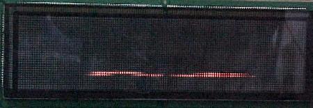
|
A Babcock 128x32 display where the 18 volt lamp matrix backbox fuse has failed. Notice the horizontal "garbage" line across the bottom center of the display. This problem only seems to affect the Babcock brand dot matrix displays. |
|
-
Interestingly, on 128x32 displays, this problem will only occurs on games with "Babcock" brand dot matrix
displays. The 128x32 displays made by Cherry and Dale seem unaffected by a failed 18 volt
backbox lamp matrix fuse. This happens because the Babcock displays require 12 volts
to function, where Cherry and Dale 128x32 displays do not. This problem can
also arise on Cherry brand 128x16 dot matrix displays.
- 12 mixed pin PCB wafer connector, Molex part# 09-18-5121.
- 12 mixed pin wire connector, Molex part# 03-09-1122.
- 6 mixed pin PCB wafer connector, Molex part# 09-18-5061.
- 6 mixed pin wire connector, Molex part# 03-09-1062.
- Male .093" terminal pins for wire connector, Molex part# 16-06-0002.
- Female .093" terminal pins for wire connector, Molex part# 16-06-0001 (new Molex part# 43080-0001).
- PIA (Peripheral Interface Adaptor) and +5 volt LED turns on immediately.
- After about 1/2 second, the PIA LED turns off.
- Blanking LED turns on next.
- +5 volt and Blanking LEDs will stay on (until the game is turned off).
This stange problem was solved with the advent of the 192x64 super-sized dot matrix display (Maverick to Batman Forever). An additional backbox 18 volt fuse (F3), bridge and capacitor was added. This backbox voltage supplied power to a switching power supply, implemented on the 192x64 DMD display driver board. This way if the lamp matrix (F2) fuse failed, the dot matrix display remained unaffected.
The Game Will Not Boot or Stops Booting.
On games Simpsons and before, the game just will
not boot. The GI lights come on (and if the game has a dot matrix display, EPROM
version is show), but little else happens. There is something wrong with the
game CPU board.
First check for +5 volts on the CPU board. The voltage range should be 4.9 to 5.1 volts. Test for this voltage at the +5 and ground test points, just to the right of the battery on the top of the CPU board. If there is good +5 volts, next check the power on LED flashes, to see if they give any information as to the cause. Turn the game on and immediately examine the LEDs.
Square Plug Power Supply Connectors.
Sometimes the square plug power supply connectors get damaged
(these connectors were used on Williams power supplies system 3 to system 11b,
and on DataEast/Sega power supply until 1995). The twelve pin 3J1 power supply
plug handles all the input voltages from the transformer to the power supply,
and often gets burned (the six pin rectangle 3J2 power supply plug is a ground
connector, and usually does not get damaged).
If the 3J1 input plug gets burnt, often the game will not even "boot".
(this plug provides the power for the +5 volt logic circuit).
As the game is first turned on,
the display will come on showing the ROM revision numbers,
and speak it's boot-up phrase, but nothing
more happens (the display turns on because this is a separate computer,
with a separate power plug).
If this 12 pin rectangle plug is burnt, the only answer is to replace it (both the PCB board wafer plug, and the wire mounted plug). Finding the part numbers for these connectors was a real bear, as they were designed in 1971! So here are the part numbers for these wafer style, mixed pin connectors.
CPU Power-On LEDs.
At power-on, the CPU board performs several self tests. While watching the LEDs (Light Emitting Diode)
on the CPU board, some information can be derived from them.
If all the self tests pass, the LEDs illuminate in the following order at power-on.
|
The three LEDs on the CPU board. |
|
|
|
The LEDs when the game is booted and running; the blanking and +5 LEDs are on. |
|
|
-
If there is a problem with the CPU when the game is turned on,
the PIA LED will usually stay on, and not turn off
(and the Blanking LED will not turn on).
Here is what this means:
- PIA LED turns ON (and stays on), blanking LED never turns on: EPROM at location 5C and/or 5B is bad.
- PIA LED turns ON, turns OFF (and stays off), blanking LED never turns on: EPROM at location 5C and/or 5B is bad (this LED sequence is very rare).
- PIA LED turns ON, turns OFF, then turns ON (and stays on), and blanking LED never turns on: 6264 RAM at location 5D is bad.
- CN17 pins 1,2,3: Ground
- CN17 pins 4,5,6: +5 volts
- CN17 pin 7: KEY
- CN17 pins 8,9: No connection
To get any more information from the LEDs, use the CPU Test EPROM (which is discussed in the section, CPU Diagnostic Test EPROM).
Bench Testing of the CPU board.
Instead of doing repair and testing of the CPU board in
the game, it is much easier to test the CPU board on the workbench.
The only voltage needed to run a DataEast/Sega CPU board is +5 volts
and ground. A switching power supply, or an old computer power supply
works great for this task. Voltage supplied must be between +4.9 and +5.1 volts DC.
Lay the CPU board on an insulted mat on the work bench. Hook up a +5 volt power supply to connector CN17, in the upper left hand corner of the CPU board. The pinouts are:
Alternatively, you can also connect +5 volts and ground to the test points on the top of the CPU board, just to the right of the battery holder. Actually this is MUCH easier than using the above connector!
|
Right next to the battery is connector CN17 and the ground and +5 volt test points. |
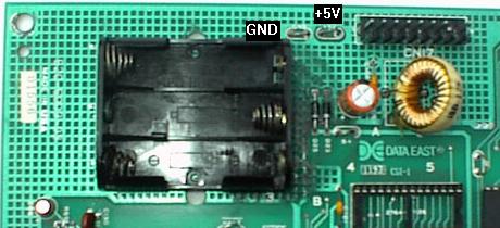
|
-
Turning the power supply on should boot the CPU board, just like
it was installed in the game. Once the CPU has booted (in attract mode), you can
check the lamp and switch matrix connectors for activity with a
logic probe. Also check the address and data lines on the
EPROMs and CPU. Here are the connectors to check:
- Switch Matrix Rows (returns): CN10 (key is pin 4). Should be HIGH.
- Switch Matrix Columns (drive): CN8 (key is pin 6). Should be PULSING.
- Lamp Matrix Rows (returns): CN6 (key is pin 4). Should be PULSING (low).
- Lamp Matrix Columns (drive): CN7 (key is pin 5). Should be PULSING.
Common Solutions to a Dead CPU.
Corroded batteries can ruin the 6808 (or 6802) CPU socket at 3D (40 pin socket),
the 6264 (or 2064C) CMOS RAM socket at 5D (28 pin socket), and the EPROM
sockets at 5B and 5C (28 pin sockets). This is very common.
Battery corrosion must be neutralized on the
printed circuit board. After the affected components are removed,
scrub the afflicted area with a mixture of 50% white vinegar and 50% water.
Then rinse the area with clear water, and let it fully air dry. Sand
any greyed areas clean, and replace the sockets and components. Check all
traces for continuity, as breaks can easily occur which are not visible.
If the game will still not boot, the most common problem is a dead 6808 (or 6802) CPU at 3D. Either CPU can be used, but the 6808 is largely unavailable (hence the 6802 is used as a replacement). Also a dead 6264 (or 2064C) CMOS RAM at 5D is very common.
Blanking Circuit Theory of Operation Service Bulletin.
Sega has a nice document explaining the theory of operation for the
blanking circuit in service bulletin number 75. To check this out, click
here and
here and
here.
3h. When things don't work: Fixing a Dead CPU using Leon's Test EPROM
-
Leon is a gentlemen from Belgium that has developed an excellent DataEast/Sega test
EPROM for diagnosing a bad CPU board. His web page is at
home.pi.be/~leonb1/dataeast/edataeast.htm.
With Leon's test EPROM, it's possible to diagnose "difficult" CPU board problems.
I have echoed much of his web page info below. Thanks to Leon for this information and the
test EPROM!
There are a few different versions of the Dataeast CPU boards. For this, only one difference is significant: which type of EPROM (27256 or 27512) is in location 5C. Download the appropriate test EPROM to use: 27512 version, or 27256 version. Using an EPROM programmer, burn this code to a blank EPROM.
The goal of his test EPROM is to test the CPU chip circuitery and its six connected PIA chips. These PIAs (6821) are used to send all signals to the external circuits, to the dot-matrix, coils, lights, and via the switch matrix to all switches (for example, PIA 8H handles the switch matrix). When the CPU and PIA's are Ok, it's almost certain that the CPU board will fully "boot", and the pinball can be further diagnosed with the internal test/diagnostic functions. If the machine still doesn't start, there is a good chance either the program EPROM or the memory RAM may have failed.
It is assumed the voltages to the CPU board are good, which can be checked with a DMM. Don't forget to do this! Only 5 volts is needed for the CPU board to "boot". If the CPU boots correctly, the middle LED (5 volt) will light and stay lit, then the right LED (PIA) will light and turn off after a half second. The third LED at the left (blanking), will then light and stay on.
First Step - Check the Voltage.
The pinball does not start, voltages have been checked using a DMM, and are Ok.
Check the voltages on the CPU board at the GND and +5 volt test points next
to the batteries.
Then check the three LEDs in the middle off the CPU board, on the right.
The +5 volt LED should be on, and probably the PIA LED too. Also sometimes the blanking LED will be
on (but not often).
|
The three LEDs on the CPU board. |
|
|
|
The LEDs when the game is booted and running; the blanking and +5 LEDs are on. |
|
|
-
Step Two - Remove the CPU board from the game.
- CN17 pins 1,2,3: Ground
- CN17 pins 4,5,6: +5 volts
- CN17 pin 7: KEY
- CN17 pins 8,9: No connection
Now take the CPU board out of the game. To avoid confusion, label the connectors as they are removed with a "sharpie" on the side of the connector.
Step Three - Connect the CPU to an External +5 volt power supply.
Once the CPU board is out, lay the CPU board on an insulted mat on the work bench and
connect it to 5 volts. An old
computer power supply works nicely for a power supply (red=+5 volts, black=ground).
On the left top of the CPU board there's a test point labeled GND and
another labeled +5 volts. Hook up the old computer power supply to
these test points. Alternatively,
hook up a +5 volt power supply to connector CN17,
in the upper left hand corner of the CPU board. The pinouts are:
|
Right next to the battery is connector CN17 and the ground and +5 volt test points. |
|
|
-
Step Four - Plug in the Test EPROM and Power-On.
With the power off, plug Leon's test EPROM (use the 27256 or 27512 version, which ever the CPU board is jumpered) into socket 5C. The test EPROM contains a program that will switch all outputs of all six PIAs to high (+5) and then low (gnd).
Step Five - Test the PIA Outputs with a Logic Probe.
With the power to the CPU board turned on,
check the outputs of the PIAs. Use a logic probe
and see if the PIA outputs go high and low. If an output is now changing states from high to low,
that PIA is malfunctioning. If none of the PIAs work, then the problem is earlier on the board (perhaps
a bad RAM or bad EPROM). The PIA LED is connected to the PIA at 11B
and when the test ROM is running, the PIA LED should flash. The same goes for blanking LED,
which will have very short flashes. So if all is good, the PIA LED will be flashing.
Now is the time to start checking the outputs of all the PIAs. This is pin 2 to pin 17, and it should go from 0 to 5 volts (which can also often be seen with a manual ranging DMM).
There are some exceptions however! The switch matrix PIA at 8H has pins 2 to 9 as *inputs*. To check this PIA, connect all pins of CN10 to ground (use some alligator clips to ground all the pins of CN10). Then pin 2 to pin 9 of PIA 8H can be read with a logic probe, and should go high and low.
The other exception is that PIA 11B. This chip has pin 9 forced to ground and cannot be read, because this pin is not used.
If a pin is found that is not alternating between high and low, short it to the (working) pin next to it. If the static pin starts to go high and low, then the PIA is broken; if both pins stop going high and low, then there's a short somewhere on the output, or the PIA itself has failed. Try to find the short, or replace the PIA.
Worst Case Scenario.
If the program doesn't work at all, we'll have to go to the source and that's the CPU chip 6802 itself.
Replace it, that's the easiest. Still a problem? Check CPU pins 2, 4, 6 and 40; they should be high (around 4 volts).
Pin 39 is the clock signal, and pin 5 is the
VMA signal, and pin 37 is the signal E (syncro for external elements). All these pins should be 2 to 3 volts
(measured with a regular DMM). These are alternating high/low signals, so here are some pictures of the
signals using an oscilloscope.
|
Left: CPU chip's clock signal at pin 39. Right: CPU chip's VMA signal at pin 5. |
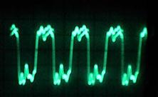
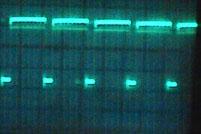
|
|
Signal E at pin 37. |
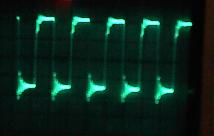
|
If one of these seven signals is different, then the problem has been found. Use the schematics to check where this signal comes from.
Still Does Not Work, What is Left?
What's left are the other outputs of the CPU: address lines (pin 9 to pin 25, except pin 21 which is ground!!),
and data lines (pin 26 to pin 33). Also the selection circuit of the test-program chip 5C and the selection
circuit chips of the PIA's. If the test program does not work, it is possible that the test-chip is not
found, or because the PIAs are not found.
Now try removing the the test EPROM out of the CPU board, and power back on. The CPU will now work *without* a program, and will execute NOP's (Non Operative instuctions), as it runs through all it's addresses starting at 0000-0000-0000-0000 to FFFF-FFFF-FFFF-FFFF. With this we can continue our test: all address lines should move high and low (pin 9 to 25, except pin 21 which is ground), and should measure about 2 volts. Do the same for the address-lines-buffers, chips 6C and 6D. There should be about 2 volts. Look for a missing signal or a short on the address lines somewhere. If necessary break some lines to find the short; bent the pin out of the socket, and look if the signal is there. If so, there is probably a short in that chip. If not, the CPU chip has failed.
Still Does Not Work: Chip selection.
What else can be wrong? Only the selection of the program chip or the PIAs.
We're still working without program chip. Because all addresses will be used, every selection address
of every PIA and EPROM will be accessed too. The selection chips are chips 8D and 8E,
and the selection of a PIA or the EPROM is made by one pin of these chips. This is
pin 23 for the PIAs and pin 20 for the EPROM 5C. Of course the selection is continued within the chips
themselves, using lower addresses, but as we've already checked the address lines we're confident they
work. This selection is done using the chips in 8E, 7E, 7C, and 8D. On the schematics at the output of 8D at the
PIA addresses 3400, 3000, 2C00, 2800, 2400, these ones you find
on pin 23 of each PIA. So each PIA's pin 23 should have about 4 volt, meaning the chip selection is Ok.
If not follow the selection signal backwards until the problem is found. Same for the selection of the EPROM at
5C, this can be found on pin 20. Tracing these signals back, is also limited, there are only two or three
chips between address lines A14 and A15, and the final selection signal which
comes out of 8D (and out of 8E, address 2200).
Data Lines.
One last case is if there's something wrong with one or more data lines.
If all the rest is Ok, then put the test EPROM back into socket 5C. The
program will run but the PIA's won't react, as no data arrives there. Data lines on the CPU chip 6802 are pin 26
to pin 33. These should go high and low, and show 2 to 3 volt. Check them after the buffer 5E,
if one is missing then look for a short. Don't forget the 6802 has already been replaced, so its output
should be Ok. Only a buffer can be broken, or there's a short on the data line. Can easily be checked by
bending up the exit pin of the buffer, and checking if the signal does come out of this pin.
If so then there is a short, if not the buffer is broken. If there is a short, then interrupt the data line
and find which IC causes the short (by breaking some lines).
This work takes a lot of time, but this really is the worst case scenario.
Now we're finishd and there is a 95% chance that the important parts of your CPU work, and the CPU board will "boot".
Other Comments.
Why not check the addresses and data lines when they arrive at the PIAs?
Because there are six PIAs, and the chance are very small that all of them will get no addresses.
So when we checked them as Ok (when leaving the address buffers), we also checked the data buffers.
The only doubt can be at the data and addresse lines which arrive at the EPROM at 5C.
This one is in a socket and can have a bad connection. So do check that.
Conclusion.
So what was wrong with my cpu-board ? The VMA signal was missing, so I bend the pin up and yes then it was present.
This meant there was a short somewhere on the VMA line. I removed the 6802 and it looked good.
There was some oxidation on a thick trace which was next to the trace at pin 5 (VMA). The oxidation caused
both traces to short, and this caused the problem. I cleaned the oxidation with a water/vinager
solution, then sanded it, and the problem was solved.
3i. When things don't work: Problems with Flippers
-
Flippers connect the player to the pinball
game. Having perfectly working flippers is extremely important. Here
are some common flipper problems and solutions.
Flippers on Laser War to Time Machine.
These conventional style flipper coils are actually two coils in one package.
The "high power" side is a few turns of thick gauge
wire. It provides low resistance, and therefore
high power. The "low power", high resistance side is many turns of much
thinner wire. This side of the coil is important if
the player holds the cabinet switch in, keeping the
flipper coil energized. The high power low resistance side of the
coil is only active when the flipper is initially energized. When the flipper is
energized and held at full extension, the low powered side
of the flipper coil is used so the coil doesn't get hot and burn.
Laser War to Time Machine used a parallel wound style flipper coil (unlike EM pinball games, which used a series wound flipper coil). This coil used an outside lug as the common lug (where both the low and high powered coil wires were connected together). Also TWO diodes were used and required on these flipper coils. This parallel wound coil eliminated the "back spike" of current when the EOS switch opened. It also allowed the use of a 2.2 mfd 250 volt capacitor to further limit EOS switch sparking and pitting. When the normally closed EOS switch opens, this removed the high powered side of the coil from the circuit. The low powered side of the flipper coil is always in the circuit, but is essentially ignored when the high powered side is in the circuit. This happens because the current takes the easiest path to ground (the low resistance, high power side of the coil). The low power high resistance side of the flipper coil doesn't get hot when the player holds the flipper button in.
Deger Designed Flipper Circuit (Playboy and later).
Starting with Playboy, DataEast changed to a single winding coil
(instead of the traditional two windings, one for low resistance high power,
and one for high resistance low power hold). The single winding coil was
delivered high voltage for the initial power, and lower voltage
for the flipper hold. When the flipper
button was pressed, 50 volts DC was directed to the single wound flipper coil. When the
normally closed EOS switch was opened, the high power was turned off. A low voltage (9 volts)
was then fed to the flipper coil, through a 1N5404 (400 volt, 3 amp) diode, mounted directly
on the coil. This allowed the player
to hold in the flipper button for as long as desired, without the
flipper coil overheating. This circuit was designed by Mr. Kurt Deger, and is hence
called the "Deger design".
|
The Deger single winding flipper coil circuit as used on Playboy and Monday Night Football only. |
|
-
For Playboy and Monday Night Football, the flipper coils had two diodes on
them. One was a standard 1N4004 "voltage snubbing" diode. This prevented
a backlash of power going backwards through the system, when the flipper
coil's magnetic field collapsed. The second diode, a 1N5404 (400 volt, 3 amp),
provided half-wave voltage rectification (changing AC to DC). This second 1N5404
diode was only used on Playboy and Monday Night Football. It was not
needed for the next generation flipper system.
Solid State Flippers (Robocop and later).
DataEast was the first company to use solid state flippers. The solid state
design again used a single winding coil (instead of the traditional two windings, one
for high voltage, and one for low voltage hold). A solid state version of the Deger design, the single winding coil had
different voltages for the initial power and the flipper hold
(only one diode, a 1N4004 voltage snubbing diode, is used). When the flipper
button was pressed, 50 volts DC is directed to the single winding flipper coil. After
a short duration (40 milli-seconds, which is not variable), the high power is turned off and
9 volts is left to hold the flipper coil. The lower 9 volts allows the
flipper button to be held, without burning the flipper coil. Note this is different
than the solid state flipper system used by Williams; which used two separate
flipper coil windings (a high and low voltage winding) to achieve this.
There were some complaints that the new solid state DataEast flippers didn't have the same feel as a traditional EOS (End Of Stroke) system flippers. This was because DataEast/Sega's design had a fixed timing (40 milliseconds) for the high voltage. On an EOS switch dependant flipper, the flippers react to the EOS switch, and turn off the high voltage accordingly.
With Jurassic Park, DataEast changed to an EOS solid state flipper design. Unlike Williams, DataEast's solid state EOS switch is normally closed (when the flipper is at rest). The amount of time the high voltage is turned on to the flipper coil is still fixed, and not controlled by the EOS switch. The EOS switch was implemented for a different reason; if the ball hit an energized flipper bat, and knocked the flipper backwards (closing the EOS switch), the flipper would be pulsed again with the high voltage for the same fixed time (this was accomplished by connecting the EOS switch in series with the cabinet flipper switch). This ensures the held flipper will stay in the up position for the player. This was done because of features implemented on Jurassic Park and Last Action Hero. The "Raptor Pit" and the "Ripper" would fire a ball back at the flipper at high speed. This EOS switch was kept for all games after Jurassic Park and Last Action Hero.
Easy Damage to the Solid State Flipper board.
The DataEast solid state flipper board(s) are not in the backbox.
They are located in the lower cabinet, below the playfield. Starting
with Ninja Turtles (the first game with playfield sliding rails, allowing the
playfield to slide forward for easier repair), flipper board damage can occur
because of the board's location. This happens
when the playfield, in the raised position, gets
tilted, and falls off the cabinet mounting slide rails. This especially
happens if the game's prop rod is used, and the playfield is
not straight on its mounting slide rails.
The best way to avoid damage is to just be careful! When raising the playfield, don't let the playfield get tilted or angled. Also try not to use the playfield prop rod. If it is used, make sure the playfield is straight on the slide rails, and won't fall inside the cabinet.
|
Damage to a solid state flipper board. This happened because the playfield fell off its mounting rails, and damaged the board. This is VERY common. Usually it tears up the flipper board much more than this! Since the SR1 and SR2 transistors with heat sinks stick out the most, they usually get ripped completely off. |
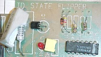
|
-
The CPU Board Flipper Relay RY1.
The flippers are only enabled during game play (and in diagnostic mode games Frankenstein and before). The flipper enable relay turns the ground off and on for the flipper coils. The flipper enable relay is located on the CPU board at RY1, and is activated by transistor Q80 (2N4401). When entering diagnostic mode (Frankenstein and before), the flipper relay should "click" on (activating the flipper buttons; this does not happen on Baywatch and later Portal diagnostic games though). This relay is a 6 vdc, 5 amp, 4 pole relay with four SPST switches. These switches are wired into 2 pairs (this is done because there can be up to 2 pairs of flippers). It connects through transistor Q80 (2N4401) and a 7402 at 12A and 12B and a 7406 at 12E and 12F, a 555 timer at 1C, and ultimately the 6821 PIA at 11D. If any of these components are bad, the relay may not activate the flippers. Test transistor Q80 first, as this fails the most often.
|
The coil diode as used on a flipper coil, Robocop and later. This lower flipper coil is on Jurassic Park, and hence has an EOS switch. |
|
|
-
If the Flipper(s) Don't Work at All...
- Solid state Flipper games (Robocop and later):
- Check the flipper fuses. For solid state flippers (Robocop and later), the fuses are on the solid state flipper board, which is on the side of the cabinet under the playfield.
- Look for damage on the solid state flipper boards. Since these boards are located below the playfield on the left side of the cabinet wall, they are very easily damaged. A common problem is a broken or open TIP36 or TIP42 transistor on the solid state flipper board. The position of the board(s) under the playfield (on the side of the cabinet), permits easy damage if the playfield tilts and falls inside the cabinet (this especially happens on Ninja Turtles and later games with playfield mounting slide rails). If the playfield falls off the slide rails and into the cabinet, it can easily tear components off the solid state flipper boards. Several transistors with heat sinks stick out the furthest from the board, making them easiest to damage.
- On Jurassic Park, Last Action Hero, and Tales from the Crypt, check the normally closed EOS switch. If the EOS switch is dirty, or has a wire or switch blade broken, or is mis-adjusted so the switch is not closed when the flipper is at rest, the flipper will not work! Test by using an alligator jumper wire across the EOS switch. This problem only happens on games with solid state flipper boards #520-5033-03 and 520-5070-00 (which is replacable with #520-5076-00 and #520-5080-00 respectively, which fixes this problem). These flipper boards can also be modified to act correctly, like the later flipper boards. See the DataEast service bulletin number 54 by clicking here, here, and here.
- Check for voltage at the flipper coil (on games WWF and later, make sure the coin door is closed!). With the flippers enabled (in game mode), use the DC voltage setting on the DMM. Put the black lead on ground (grounding strap inside the coin door). Put the red lead on the flipper coil lug connected to the BANDED side of the diode. Press and hold the cabinet flipper button (no voltage will be shown until the cabinet button is pressed). The DMM should show a spike of high voltage, which settles down to about 7 volts DC No voltage means a fuse is blown, or there is damage to the solid state flipper board, or the flipper enable relay. Repeat this step in attract (game over) mode. But this time put the red lead on either flipper coil lug. With the flipper cabinet button pressed and held, look for a voltage spike which settles down to about 7 volts DC.
- If there is no power to a flipper, and the solidstate flipper board fuses are good, next test the TIP36 transistors on the flipper board. Even if they do not appear to be damaged, this is a common part to fail. If a TIP36 fails, its associated flipper will not function at all. See Checking/Fixing Transistors and Coils for procedures on testing transistors.
- Pre-Solid State Flipper games (Monday Night Football and before):
- Check the flipper fuses. For pre-solid state flippers (Monday Night Football and before), the flipper fuses are in the backbox.
- Make sure the EOS switches are properely adjusted! For example, if an EOS switch never opens, the flipper fuse will continually fail. Make sure this normally closed EOS switch is adjusted properely with a 1/8" to 1/16" gap at full flipper extention.
- Clean the flipper cabinet switch contacts and the EOS switch contacts with a small metal file. This will ensure good contact on these switches, and decrease any resistance from burnt or pitted switch contacts.
- VERIFY THIS. For pre-solid state flippers (Monday Night Football and before), check for +50 volts at the flipper coil. With the flippers enabled (in game mode, or game in diagnostic mode on some games), put the DMM on DC voltage. Put the black lead on ground (grounding strap by the playfield prop rod). Put the red lead on any of the flipper coil lugs. The DMM should show between 50 and 80 volts. No voltage means a fuse is blown, or a wire has broken, or damage to the flipper enable relay.
- VERIFY THIS. Test the coil itself. On pre-solid state flippers (Monday Night Football and before) turn the game on and go into diagnostic mode. Attach an alligator test lead to ground (grounding strap by the playfield prop rod), and momentarily touch the other end of the test lead to the non-banded diode coil lug. The coil should activate.
- All Games:
- Check the flipper fuses. For pre-solid state flippers (Monday Night Football and before), the flipper fuses are in the backbox. For solid state flippers (Robocop and later), the fuses are on the solid state flipper board, which is on the side of the cabinet under the playfield.
- Check the flipper coil. With the DMM set to
ohms and the game turned off:
- On a three lug (pre-Deger, Time Machine and before) coils, put one lead of the DMM on the common flipper lug (the one with the thick and thin coil winding attached to it).
- Put the other lead of the DMM on the thick wire lug. The DMM should show between 4 and 6 ohms. This is the high powered side of the coil.
- Move the DMM lead to the thin wire lug of the coil (if a 3 lug coil). The DMM should show a little more than 4 to 6 ohms until the flipper is manually moved to the full extended position, opening the EOS switch. The DMM should then show about 160 ohms. Note if more than about 5 ohms is shown when the flipper is at rest, the EOS switch is pitted and causing some resistance. Clean it for stronger flippers.
- On Playboy and later (Deger flipper coil design) games, just put the DMM on both leads of the flipper coil. The DMM should show between 4 and 6 ohms.
- If the DMM does not show approximately these readings, the flipper coil is bad. On pre-Deger flipper coils, typically the hold side of the coil goes bad more often that the power side.
- Test the flipper diode(s). Cut one lead of the diode off the coil lug. Set the DMM to the diode setting. Put the black lead of the DMM on the banded side of the diode. It should show .4 to .6 volts. Reverse the leads and no reading should be shown. When done, re-attach each diode lead.
- The CPU board flipper relay RY1 is not engaging. If the relay that turns the ground on to the flippers (when a game starts) has failed, the flippers will never work. Check for cold solder joints on the relay's solder points. Test transistor Q80 (2N4401), as this fails the most often.
- Flipper goes up, but won't stay up. On solid state flipper games, check the hold fuses on the flipper board. On solid state flipper games Robocop and Phantom of the Opera, check resistors R16 and R32 on the flipper board; these should be 100 ohm 1/4 watt resistors. Also check resistors R7 and R23; these should be 1000 ohm 1/4 watt resistors.
- Flipper works for a few minutes, then doesn't work at all. Check the flipper enable relay RY1 on the CPU board. Cold solder joints on this relay, or bad relay switch contacts can cause this problem.
- On pre-Deger (Time Machine and before) flipper coils, this means the hold winding on the coil itself is broken. The hold winding on the coil is the thin wire. If it is broken, the loose wire can usually be seen, and has broken away from one of the solder lugs (the middle lug should have both the thick and thin wire attached to it). Test the coil first (see above) before replacing the transistor.
- On Deger (Playboy and later) flipper coils, make sure the normally closed EOS switch is working correctly. Also check the IN5404 diode for failure.
- When activated, doesn't hold up (the flipper "flutters"). On all solid state flippers, check the fuses on the solid state flipper board(s). Also check the TIP32c transistors which control the hold voltage.
- On solid state flipper games Phantom of the Opera and before, check the flipper cabinet buttons. During production of Phanton of the Opera, the flipper buttons were changed from leaf switches to enclosed micro switches. This prevented the leaf switches from getting dirty, and causing this problem.
- Rebuild the flippers. Play and wear in the flipper parts is the primary reason for weak flippers. A mushroomed flipper plunger dragging against the coil sleeve is a classic cause of weak flippers.
- Make sure there is about 1/32" to 1/16" up and down play on the flipper shaft. To test this, from the top of the playfield, grap the plastic flipper and pull up. There should be some play. If not, the flipper could be binding on the nylon playfield insert. This gap is adjustable from under the playfield by changing the flipper pawl's grip on the flipper shaft.
- On pre-Deger flippers, clean the EOS switch contacts and the cabinet flipper switches. These are high-voltage tungsten switch contacts, and need a metal file to clean them. These switch contacts often become pitted and tarnished, and resistance develops.
- Check the fuses. The right and left flipper board fuses could be OK, but if another 50 volt fuse is blown elsewhere on the game, that could affect the flippers (this will affect both flippers equally).
- On solid state flipper games Robocop and Phantom of the Opera, check resistors R7 and R23; these should be 1000 ohm 1/4 watt resistors.
- On Tales from the Crypt, some flipper boards were released with the wrong value resistor at position R36. This will affect the pulse width of the 50 volt drive signal, which gives the flipper its "kick". Resistor R36 should be a 2.2 meg ohm (some boards were released with 2.2k ohms installed instead). This was mentioned in service bulletin number 57.
- Check the bridge and capacitor that supply voltage for the flipper coils. An open diode in the bridge rectifier that supplies power to the flippers can cause weak flippers. A fatigued or cracked solder joint on this bridge (or its associated capacitor) can do that too. This is rare, but can happen. This problem will affect BOTH flippers equally. See the section, Testing Bridge Rectifiers for more information.
- On pre-Deger (Time Machine and before) flippers, check the EOS switch to make sure
it is adjusted properely (1/8" gap at full flipper extension),
and that the contacts are clean and filed. If the coil is getting
hot, this means the EOS switch is not opening,
or the EOS switch capacitor has shorted on.
- Electrical: On Deger (Playboy, Monday Night Football) and
solid state flipper games (Robocop and later),
check/replace the flipper coil diode. If the flipper coil diode
is broken or shorted on, the flipper coil will
stay energized after first using the flipper(s). Replace this diode with
a new 1N4004 or 1N4007 diode.
The counter EMF (Electro-Motive Force) produced
by the magnetic field in the coil collapsing is a reverse polarity voltage. This
reverse polarity voltage can also cause damage to the solidstate flipper board.
If the solidstate flipper(s) are still stuck in the Up position, then check the solidstate flipper board's TIP36 and TIP32 transistors. The TIP36 transistors supply the initial power voltage to the flipper coils, and can be easily damaged. The TIP32 transistors supply the "hold" voltage to the flipper coils (and hence are not as easily damaged as the TIP36 transistors). Both TIP transistor types are easily checked with a DMM, see the transistor section for more details). If a TIP36 has failed, it will usually hold the flipper "up" as soon as a game is started (or sooner!) If the flippers are still stuck in the up position, but only after the flipper button is initially pressed, check the S2800B Silicon Controlled Rectifiers. Often the SCRs will "gate" in the holding voltage circuit, causing the flipper to remain energized as if the player was holding the cabinet flipper button in. This was mentioned in service bulletin number 58.
- Mechanical: Flipper is too tight inside the playfield flipper bushing. This causes binding between the playfield bushing and the flipper crank assembly. There should be about a 1/16" to 1/32" gap. If the flipper paddle doesn't have any vertical movement, it's too tight. Use the flipper adjustment tool included with the game to fix this (see rebuilding flippers for more info).
- Mechanical: On games with an EOS switch (pre-Deger Time Machine and before, and Jurrasic Park and later), check the EOS switches and the flipper pawl. Often the rubber coating on the flipper pawl that contacts the EOS switch will wear. This causes the flipper pawl to hang up on the end of the EOS switch. The end of the EOS switch can even get torn and fray from metal-to-metal contact. See "Rebuilding Flippers" for information on fixing this.
- Mechanical: Check the flipper return spring. Is it broken, missing or maladjusted? On games Jurassic Park and Last Action Here, DataEast put a "crimp" in the flipper return spring's attachment point. This causes the flipper spring to break easily. DataEast identified this in service bulletin number 46.
If the Flipper Works, but...
The Flipper "Flutters"... (When the flipper button is pressed and held, flipper doesn't hold up, but "flutters" up and down quickly).
If One or Both Flippers are Weak...
Flipper Coil Gets Very Hot...
Before proceeding with repair, first determine if the stuck flipper is a mechanical or electrical problem. If the flipper is stuck in the "up" position, turn the game off. Does the flipper return to its normal "down" position? If so, the problem is electrical. Otherwise if the flipper stays up even when the game is turned off, then the problem is mechanical.
|
Solid state flipper problem flow chart. |
|
Weak Flippers or "Double Flips" on game Robocop, Phantom of the Opera.
DataEast released a service bulletin on these games regarding a
rare problem of weak flippers, or flippers that "double flipped". If this problem is
seen on these games, check service bulletin number 23 by clicking
here,
here,
here, and
here.
Flippers don't work (and Neither do the Special Coils).
The flippers just do not work during game play, and all
or some of the special coils (pop bumpers, slingshots) do not
work either. If the fuses are OK, check the chips at locations
12B and 12A (7402). Often the chip at 12B will fail, causing
the flippers and the special coils to not work. The chip at
12B is also used to enable "blanking". If this chip has failed,
often the CPU will not even boot properely.
Game won't allow entry of High Score Initials.
On games Monday Night Football and before without solid state flippers,
there is a second switch on the flipper EOS switch stack that is connected to the
switch matrix. This switch often goes out of adjustment, preventing
the high score intials from being entered. This will also affect the lane
change operation (if the game uses that). If this normally open switch is out of adjustment
(permanently closed or open), the player will not be able to enter their
high score initials with the flipper buttons.
|
Left: Monday Night Football and before: the EOS flipper switch on these games is actually two switches. The switch on the left (with the diode) is low-voltage and connected to the switch matrix. This normally open switch closes when the flipper is activated, and controls the lane change and high score initials. The switch on the right is the high-voltage flipper EOS switch. A nylon space insulates the two switches from each other. Right: Starting with Robocop (solid state flippers), the lane change/high score switch were moved to the cabinet flipper buttons. This second switches with the nylon spacer is still part of the switch matrix. Since the cabinet switch is now a low voltage switch, there was good reason to move the switch from the flipper coil to here. |
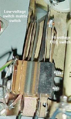 Ā Ā Ā Ā
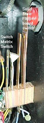
|
-
On games with solid state flippers (RoboCop and later),
the entry of high score initials (and lane change, if the game has that) is
still controlled by the switch matrix. Only the location of the switches
changed to the flipper cabinet buttons.
End of DataEast Repair document Part Two.
* Go to DE/Sega Repair Part One
* Go to DE/Sega Repair Part Three
* Go to the Pin Fix-It Index at http://marvin3m.com/fix.htm
* Go to Marvin's Marvelous Mechanical Museum at http://marvin3m.com