- DE Schematics (1.4meg). DataEast "Checkpoint" schematics in a single ZIP (WinZip required) file (see game specific information below for board generations used in Checkpoint, and if they match your specific game). Individual scans are in TIF format.
- www.sternpinball.com/schematics.htm. Mostly newer schematics for games not covered in this manual.
- www.sternpinball.com/bulletins.htm. All the DataEast/Sega/Stern Service Bulletins.
- www.sternpinball.com/parts.htm. Appendix A through I of the more recent game's manual
- Work Light: clamp style lamp
- Screwdrivers: small and medium size, phillips and flat head
- Nut Drivers: 1/4", 5/16", and 11/32"
- Wrenches: 3/8", 9/16", 5/8" required, other sizes suggested
- Allen Wrenches: get an assortment of American sizes
- Needle Nose Pliers
- Hemostat. Handy for holding parts and springs. Best to have both the curved and straight versions if possible.
- Soldering Iron.
- Rosin Core 60/40 Solder.
- De-soldering tool.
- Digital Multi-Meter (DMM).
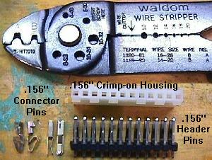
- Hand Crimping Tool: Molex WHT-1921 (part# 11-01-0015), Molex part# 63811-1000, Amp 725, or Radio Shack #64-410.
- Alligator clips and wire.
- Novus #2 (for cleaning playfields and ramps). The recommended cleaning product by DataEast/Sega, as described in service bullentin 38a.
- Novus #3 (for polishing metal parts)
- Johnson's Paste Wax or Trewax (for waxing playfields and cleaning rubber)
- #47/#44 light bulbs: have 20 or so around. Fifty is plenty to do most games. Number 47 bulbs are suggested instead of #44 bulbs, as they consume less power and produce less heat. They also put less stress on illumination circuits and connectors. Since they are less bright, a good compromise is to use #44 bulbs for the computer controlled lights, and #47 bulbs for the general illumniation.
- #555 light bulbs: have 20 or so around. Fifty is plenty to do most games.
- #906 or 912 flash bulbs: have 10 or so around.
- #89 flash bulbs: have 10 or so around.
- Fuses: have five of any needed value on hand at all times.
Get 250 volt fuses, not 32 volt. Radio Shack sells fuses for a decent price. Slow-blo fuses are known as MDL fuses. Fast-blo fuses are known as AGC fuses. At minimum: 1/4 amp slo-blo, 1/2 amp slo-blo, 2 amp slo-blo, 4 amp slo-blo, 5 amp slo-blo, 7 amp slo-blo, 8 amp fast-blo. - Nylon Coil Sleeves: the longer 2 3/16" length (Stern part# 545-5388-00, Wms part# 03-7066-5) are used when rebuilding flippers. The 1.75" length (Stern part# 545-5031-00, Wms part# 03-7066) are used for pop bumpers, etc. Sleeves with a lip (Stern part# 545-5076-00, Wms part# 03-7067-5) and tubing on each side (known as an "inline" sleeve) are used on kickers, knocker, etc.
- Flipper Plunger/Link: used when rebuilding flippers. Stern part# 515-5822-00, Williams part# A-15847 or A-10656.
- Flipper Link Spacer Bushings: these small bushings go inside the flipper links. Stern part# 530-5139-00.
- Flipper playfield nylon busing: Stern part# 545-5070-00.
- Entire flipper plunger, link and flipper pawl. Stern part# 515-5051-00 (same for both right and left side). This is the "old style" flipper pawl; the new style flipper parts (starting with Apollo13) are not interchangable with the older style parts.
- Flipper Coil Stops: used when rebuilding flippers. Stern part# 515-5346-00.
- Flipper Plastic Actuator: high wear part, activates the EOS switch. Stern part# 545-5084-00. Not included with the flipper pawl (515-5051-00) assembly.
- Flipper EOS Switch: Stern part# 180-5124-01.
- 1 1/16" Pinballs: a new pinball will make the playfield last longer.
- Leg Levelers: replace those old crummy looking leg levelers with brand new ones. 3" are used on solid state games.
- Rubber Rings: order game-specific ring kits with exactly the rings needed. Don't forget flipper rubbers and a shooter tip.
- Transistors: keep a few TIP102, TIP42, TIP36c, TIP32c, 2N3906, 2N3904, 2N4401, 2N5060 transistors around.
- Diodes: keep a few 1N4004 diodes around.
- Bridge Rectifiers: keep an extra 35 amp, 200 volt (or higher) bridge rectifier around, with lug leads. The industry part number is MB3502, Stern part# 112-5000-00.
- 6821 PIA chip: have several around as the CPU board uses 6 of these PIA (Peripheral Interface Adaptor) chips.
- 6808 or 6802 CPU chip: have either one around for the CPU board. The 6802 is much easier to find (and more versatile), as the 6808 is largely unavailable (the 6808 is a 6802 without the onboard RAM). Either works equally well.
- 2064C or 6264 CMOS RAM chip: have either one of these around for the CPU board.
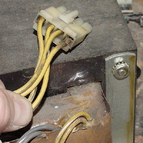
- Connector pins and housings: used to repair burnt connectors. Molex .156" style connectors are most commonly used on these games.
- Sockets: 28 and 40 pin sockets for the above chips.
- Version 1 (#520-5003-01): Only used for part of the production of DataEast's first game (Laser War). The RAM at location 5D is a 2K (24 pin) 6016 RAM.
- Version 2 (#520-5003-02): Used from Laser War (partial production) to Phantom of the Opera. The RAM at location 5D is an 8K (28 pin) 6064 RAM.
- Version 3 (#520-5003-03): Used from Back to the Future to Batman Forever. Uses "non-reflexive" (CPU controled) circuitry for the kickers and pop bumpers. Version 3b (my term) is the same as Version 3, but 3 extra pins added at connector CN3 for a printer option (Last Action Hero to Batman Forever).
- jumper J4 installed.
- jumber J5 removed
- jumper J4 removed.
- jumper J5 installed.
- J1=Clock speed
- J2/J3=Address line 14, high or connected to the CPU.
- J4/J5=Address line 15, high or connected to the CPU.
- J6=unknown
- J7=IRQ speed
- J8=PIA 11B port A7 (used for the blanking circuit)
1a. Getting Started: An Introduction to DataEast/Sega Pinball
-
DataEast pinball (then Sega pinball, and now Stern Pinball!) is really a Gary Stern company.
Mr.Stern is a very smart businessman. His approach to business is,
"copy the industry leader". At the time when DataEast started out in 1987, Williams
was the industry leader of pinball. Hence Mr.Stern copied Williams. So
closely, that DataEast's system of pinball circuit boards
resembled Williams' system at that time (System 11).
Keep this in mind when repairing
any 1987 to 1995 DataEast/Sega pinball. Stern (DataEast/Sega) is the
industry leader now!
1b. Getting Started: Experience, Schematics
-
What Repair Experience Is Expected?
Little experience in fixing pinballs is assumed. Basic electrical knowledge is helpful, but not necessary. It is assumed you can solder and use the basic features of a Digital Multi-Meter (DMM) such as measuring voltage and resistance. Please see http://marvin3m.com/begin for details on the basic electronics skills and tools needed. This document should help if you just bought your first (or second, or third) pinball "as-is", and hope to fix it.
Got Schematics?
Having a schematic for the game would be ideal, but sometimes it can be fixed
without it. Schematics can be ordered from one of the sources on the
suggested parts & repair sources web page.
Note this repair guide is NOT a replacement for the game manual and schematics!
Schematics are available on the internet too. Adobe Acrobat is needed to view most files.
1c. Getting Started: Necessary Tools
-
Fixing electronic pinball games will require a few tools. Luckily, most
are not that specialized and are easy to get.
Non-Specialized Tools Required:
Specialized Tools Required:
These are electronics tools needed for most repairs. Please see http://marvin3m.com/begin for details on the basic electronics tools needed.
Cleaning "Tools" Required:
1d. Getting Started: Parts to Have On-Hand
-
When fixing electronic pinballs, it is highly recommended having some parts
on-hand to make things easier and cheaper. All these parts are
available from a pinball retailer.
Parts to have:
Order the transistors and diodes from many sources as listed on the suggested parts & repair sources web page.
1e. Getting Started: Different Board Generations
-
Knowing what board generations are in your game is important. This information
will allow swaping of boards between games for testing.
CPU Board Generations.
There are three different "official" generations of the DataEast pinball CPU systems.
All boards use a 6808 (or 6802) CPU chip, and are essentially a copy of Williams' System 11
CPU board (without the on-board sound circuitry).
These are known as Version 1, Version 2, and Version 3. There is actually one other slightly
different version of Version 3, which I call version "3b".
All DataEast/Sega CPU boards are downward compatible (so Version 3 could be used in a Version 1 or Version 2 game). However, it is not possible to use a CPU Version 2 board in a Version 3 game, since the non-reflexive (CPU controlled) special coil circuitry used in Revision 3 does not exist in a Version 2 CPU board. Also, to modify a Revision 3 CPU board to work in Laser War (Revision 1), some modifications to the board must be performed. Check out DataEast service bulletin number 6 for this modification, by clicking here.
CPU Jumpers.
Depending on the number and size of EPROMs installed on the CPU board,
different jumpers need to be set. This is especially the case when
moving the CPU board to a different game.
Essentially there are only two jumpers used in all DataEast/Sega games: J4 and J5. These two jumpers dictate the size of the CPU EPROM used at location 5C. On games Laser War to Batman, jumper J4 should be installed and jumber J5 removed (these games use a 27256 at location 5C, and a 27128 or a 27256 at 5B). On games Star Trek 25th to Batman Forever (which uses a single 27512 EPROM at 5C and no EPROM at 5B), jumper J5 should be installed and jumper J4 removed.
To sumarize...
27256 at location 5C, and a 27128 or 27256 at location 5B (typically games Laser War to Batman):
27512 EPROM at location 5C, no EPROM at location 5B (typically games Star Trek 25th to Batman Forever):
There are addtional CPU jumpers, but they should never be changed. Here is the list of all the jumpers, and their functions:
| CPU Jumper Table | ||||
|---|---|---|---|---|
| Game | CPU Rev |
EPROM Position |
Jumpers INSTALLED |
Jumpers REMOVED |
| Laser War | ||||
| 1 | 5C | J4, J6a, J7a | J5, J6, J7b | |
| 2 | 5B, 5C | J4, J5a, J6a | J5, J5b, J6b | |
| � | ||||
| Secret Service | 2 | 5B, 5C | J4 | J5 |
| Torpedo Alley | 2 | 5B, 5C | J4 | J5 |
| Time Machine | 2 | 5B, 5C | J4 | J5 |
| Playboy 35th Anniversary | 2 | 5B, 5C | J4 | J5 |
| Monday Night Football | 2 | 5B, 5C | J4 | J5 |
| Robocop | 2 | 5B, 5C | J4 | J5 |
| Phanton of the Opera | 2 | 5B, 5C | J4 | J5 |
| Back to the Future | 3 | 5B, 5C | J4 | J5 |
| Simpsons | 3 | 5B, 5C | J4 | J5 |
| Checkpoint | 3 | 5B, 5C | J4 | J5 |
| Teenage Mutant Ninja Turtles | 3 | 5B, 5C | J4 | J5 |
| Batman | 3 | 5B, 5C | J4 | J5 |
| � | ||||
| Star Trek 25th Anniversary | 3 | 5C (27512) | J5 | J4 |
| Hook | 3 | 5C (27512) | J5 | J4 |
| Lethal Weapon 3 | 3 | 5C (27512) | J5 | J4 |
| Star Wars | 3 | 5C (27512) | J5 | J4 |
| Rocky & Bullwinkle | 3 | 5C (27512) | J5 | J4 |
| Jurassic Park | 3 | 5C (27512) | J5 | J4 |
| Last Action Hero | 3 | 5C (27512) | J5 | J4 |
| Tales from the Crypt | 3 | 5C (27512) | J5 | J4 |
| Tommy | 3 | 5C (27512) | J5 | J4 |
| WWF Royal Rumble | 3 | 5C (27512) | J5 | J4 |
| Guns N' Roses | 3 | 5C (27512) | J5 | J4 |
| Maverick | 3 | 5C (27512) | J5 | J4 |
| Frankenstein | 3 | 5C (27512) | J5 | J4 |
| Baywatch | 3 | 5C (27512) | J5 | J4 |
| Batman Forever | 3 | 5C (27512) | J5 | J4 |
| Game | CPU Rev |
EPROM Position |
Jumpers INSTALLED |
Jumpers REMOVED |
- #520-5033-00: Robocop to Rocky & Bullwinkle. Supports two flippers, and did not use an EOS switch on the flipper coils (this version was also used as a test on about 100 Playboy 35th games, and 100 Monday Night Football games).
- #520-5033-03: Jurassic Park, Tales from the Crypt. Supports three flippers, and uses an EOS switch on the flipper coils. This board had a design error such that if the EOS switch was broken, then the flipper would not work. Hence it was replaced by #520-5076-00.
- #520-5070-00: Last Action Hero only. Supports two flippers, and uses an EOS switch on the flipper coils. This board had a design error such that if the EOS switch was broken, then the flipper would not work. Hence it was replaced by #520-5080-00.
- #520-5076-00: Jurassic Park to Batman Forever. Supports three flippers and EOS switches on the flipper coils. Can be used on Jurassic Park and Tales from the Crypt to replace #520-5033-03.
- #520-5080-00: Only used on WWF Royal Rumble and Baywatch (plus Apollo13 and Goldeneye, but these are "Whitestar" version games and not covered in this guide). Supports two flippers with EOS switches. Can also be used on Last Action Hero to replace #520-5070-00.
- On the component side of the flipper board 520-5080-00, find the connector labeled CN1. Cut the extruding pin number 10 completely off of the board, so it cannot connect to the wiring harness. For reference, pin 2 is the "key" pin.
- On the solder side of the flipper board, add a jumper wire across capacitor C10. This will essentially short out the capacitor, rendering it useless. This capacitor is located right next to the CN1 pin 10, which was cut in the previous step.
- On the solder side of the flipper board, add a jumper wire between connector CN1 pin 1 and pin 2. For reference, pin 2 is the "key" pin.
- On the solder side of the flipper board, add a jumper wire between connector CN1 pin 6 and pin 7. For reference, pin 2 is the "key" pin.
- On the solder side of the flipper board, there is a trace on connector CN1 that runs from pin 2 to pin 7. Cut this trace with an Exacto knife. For reference, pin 2 is the "key" pin.
- Label the board as modified and for use in games without EOS switches.
- #520-5000-00: used from Laser War to the Simpsons. This power supply was designed to be used with alpha-numeric score displays.
- #520-5047-00: used from Checkpoint to Hook. This power supply was designed to be used with the small (128x16) dot matrix score display.
- #520-5047-01: used on Lethal Weapon 3, Star Wars, and Rocky & Bullwinkle only. These are two flipper, large (128x32) dot matrix score display games.
- #520-5047-02: used from Jurassic Park to Guns N' Roses. This power supply supported three flippers and the larger (128x32) dot matrix score display.
- #520-5047-03: used on Maverick to Batman Forever, and supported the super-size (192x64) dot matrix score display.
- The first system of score displays was only used on Laser War. It had a master display board (#520-5004-00) which controlled all the displays through other slave display boards. This included two 7 digit 16 segment alpha-numeric displays (display boards #520-5005-00), two 7 digit 7 segment numeric displays (display boards #520-5006-00), and one 4 digit 7 segment numeric display (display board #520-5007-00).
- Four combined 7 digit 16 segment alpha-numeric displays: used from Secret Service to Playboy. Display board #520-5014-01.
- Two 16 digit 16 segment alpha-numeric displays: used from Monday Night Football to the Simpsons. Display board #520-5030-00.
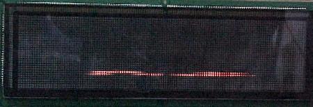
- Small 128x16 line dot matrix display: used from Checkpoint to Hook. Display board #520-5042-00.
- Large 128x32 line dot matrix display: used from Lethal Weapon 3 to Guns N Roses. This "normal" sized dot matrix display used display board #520-5052-00.
- Super-sized 192x64 dot matrix display: used from Maverick to Batman Forever. Display board #520-5075-00.
- #520-5015-00: MRB board, used from Laser War and Secret Service only. No 50 volts handled by this board (and hence, no TIP36c transistors).
- #520-5021-00: PPB board, used from Torpedo Alley to Jurassic Park. Easily identified because it has six fuses. Handles 50 volt power, and holds five TIP36c transistors which are used to ground the 50 volt coils.
- #520-5021-05: PPB board, used from Jurassic Park (late in the production run) to Batman Forever. Easily identified because it has nine fuses.
- #520-5002-00: only used on Laser War, for part of the production. Used 27256 EPROMs.
- #520-5002-02: used from Laser War to Back to the Future. Only difference between this boards and the prior -00 variant is the size of the sound EPROMs they address. This version used both 27256 and 27512 EPROMs.
- #520-5002-03: used on the Simpsons, Checkpoint, and Teenage Mutant Turtles. This board allowed the two voice EPROMs to be as large as 27010 EPROMs.
- #520-5050-01: used from Batman to Lethal Weapon 3. Allowed the voice EPROMs to be as large as 27020.
- #520-5050-02: used on Star Wars, Rocky & Bullwinkle, and Jurassic Park. This sound board allowed the voice EPROMs to be as large as 27040.
- #520-5050-03: used on Last Action Hero, Tales from the Cyrpt, and Maverick. Very similar to the -02 generation (addressing 27040 EPROMs). No further info known on this board.
- #520-5077-00: used on Tommy, WWF, Guns N Roses, and Frankenstein. This board was a completely new design, and allowed up to four 27040 voice EPROMs.
- #520-5126-02: used on Baywatch and Batman Forever. No further info known on this board.
- Checkpoint to Hook (128x16 dot display): Z80A CPU. This dot matrix controller is mounted right to the back of the dot matrix score display glass itself.
- Lethal Weapon to Guns N Roses (128x32 dot display): 68B09 CPU on a separate controller board mounted behind the display glass, #520-5055-00 (Leathal Weapon to Last Action Hero) or #520-5505-01 (Tales from the Crypt to Guns N Roses).
- Maverick to Batman Forever (192x64 dot display): 68000 CPU on a separate controller board mounted behind the display glass, #520-5092-01.
Deger Design Flipper Circuit.
Starting with Playboy, DataEast changed to a single winding coil
(instead of the traditional two windings, one for low resistance high power,
and one for high resistance low power hold). The single winding coil had
high voltage delivered for the initial power, and lower voltage
for the flipper hold. When the flipper
button was pressed, 50 volts DC was directed to the single wound flipper coil. When the
normally closed EOS switch was opened, the high power was turned off. A low voltage (9 volts)
was then supplied to the flipper coil, through a 1N5404 (400 volt, 3 amp) diode, mounted directly
on the coil. This allowed the player
to hold in the flipper button for as long as desired, without the
flipper coil overheating. This circuit was designed by Mr. Kurt Deger, and is hence
called the "Deger design".
|
The Deger Design single winding flipper coil circuit as used on Playboy and Monday Night Football only. |
|
-
For Playboy and Monday Night Football, the flipper coils had two diodes on
them. One was a standard 1N4004 "voltage snubbing" diode. This prevented
a backlash of power going backwards through the system, when the flipper
coil's magnetic field collapsed. The second diode, a 1N5404 (400 volt, 3 amp),
provided half-wave voltage rectification. This second 1N5404
diode was only used on Playboy and Monday Night Football. It was not
needed for the next generation flipper system.
Solid State Flipper Board (SSFB) Generations.
DataEast was the first company to use solid state flippers. This solid state
design again used a single wound coil (instead of the traditional two windings, one
for high voltage, and one for low voltage hold). A solid state version of the Deger design, the single wound coil had
different voltages for the initial power and the flipper hold
(only one diode, a 1N4004 "voltage snubbing" diode, was used). When the flipper
button was pressed, 50 volts DC was directed to the single wound flipper coil. After
a short duration (40 milli-seconds, which was not variable), the high power was turned off and
9 volts was left to hold the flipper coil. The lower 9 volts allowed the
flipper button to be held, without burning the flipper coil. Note this was different
than the solid state flipper system used by Williams; which used two separate
flipper coil windings (a high and low power winding) in their design.
DataEast put out a nice service bulletin on the operations of their solid state flipper design. This is bulletin number 49, and is available by clicking here, and here.
There were some complaints that the new solid state DataEast flippers didn't have the same feel as a traditional EOS (End Of Stroke) system flipper. This was because DataEast/Sega's design had a fixed timing (40 milliseconds) for the high voltage (unlike Williams games, whose electronic flippers reacted to the EOS switch, and turned off the high voltage accordingly).
With Jurassic Park, DataEast implemented an EOS solid state flipper design. Unlike Williams, DataEast's solid state EOS switch was normally closed. The amount of time the high voltage was turned on to the flipper coil was still fixed, and not controlled by the EOS switch. The EOS switch was implemented for a different reason. When the ball hit an energized flipper bat, and knocked the flipper backwards (opening the EOS switch), the flipper would be pulsed again with the high voltage for the same fixed time (this was accomplished by the EOS switch connected in series with the cabinet flipper switch). This ensured the held flipper would stay in the up position for the player. This was done because of features implemented on Jurassic Park and Last Action Hero. The "Raptor Pit" and the "Ripper" would fire a ball back at the flipper at high speed. This EOS switch was kept for all games after Jurassic Park and Last Action Hero.
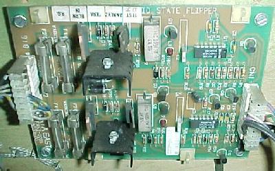
|
A pair of solid state flipper boards on the left inside of the cabinet, below the playfield. Note the back flipper board still has its factory original cardboard shorting cover. These are flipper board #520-5080-00, as used on WWF and Baywatch. |

|
-
Solid state Flipper Board Problems on JP, LAH, TftC.
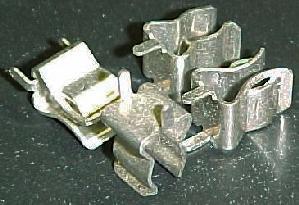
On the games Jurassic Park, Last Action Hero, and Tales from the Crypt there is a design problem with their flipper boards, #520-5033-03 (3 flippers, used on JP and TftC) and #520-5070-00 (2 flippers, used on LAH). Games with these board use a normally closed EOS switch on the two lower flippers (only). If an EOS switch is broken or mis-adjusted so it is not normally closed, its corresponding lower flipper will not work (but the upper flipper, if the game has one, will work). This problem was corrected with version #520-5076-00 (3 flippers) and #520-5080-00 (2 flippers), as used on games Tommy and later. The newer #520-5076-00 and #520-5080-00 are backwards compatible. Additionally, starting with Tales from the Crypt, the EOS switch became more robust. This newer EOS switch design is easy to identify because of a "bend" near the end of the switch blade.
With the start of Tommy production (after JP, LAH and Tales from the Crypt), the flipper board and EOS switch changed again. The new 3 flipper board (#520-5076-00) is backwards compatible to JP and TftC's flipper board (#520-5033-03). The new 2 flipper board (#520-5080-00) is backwards compatible to LAH's flipper board (#520-5070-00). These new revisions removed the broken EOS switch problem.
The JP, LAH and TftC flipper boards can be modified to work correctly, like the later flipper boards. DataEast service bulletin number 54 describes this procedure. To view this service bulletin, click here, here, and here.
Flipper board evolution:
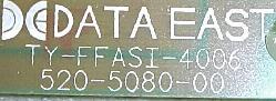
As interesting trivia, the acronym "TY-FFASI" can be seen silk screened on many of these solid state flipper boards. In the early 1990s, Williams was suing DataEast for a range of things, from board design to playfield plagiarism. DataEast responded with this acronym, which means, "take your fu**ing flippers and stick it".
|
A special note to the lawyers at Williams gaming, silk screened on many solid state flipper boards. |
|
-
Using a Newer Flipper Board on Playboy to Rocky & Bullwinkle.
Games Robocop to Rocky & Bullwinkle (or Playboy and Monday Night Football test games) do not use an EOS switch for the solid state flipper board #520-5033-00. The newer flipper board #520-5080-00 (which supports an EOS switch) can be adapted to work on these older games. The original board 520-5033-00 is no longer available too, so this modification is important if the entire flipper board on these older games needs replacing.
Here are the modifications steps to use the newer flipper board 520-5080-00 in older non-EOS switch games:
Power Supply Board (PSB) Generations.
Power supply boards were changed when different score display power requirements were
needed (or the number of flippers changed). Because of this, power supply boards
are NOT downward or upward compatible! QUESTION FOR JOE: Apparently most
power supplies used in Lethal Weapon and later are labeled "520-5047-00 REV X".
The "X" in the "REV" seems to be A, B or C. Is "REV C" the same as "520-5047-03"?
Score Display & Display Board Generations.
DataEast had several interesting innovations regarding displays. They were
the first pinball company to use a dot matrix display (DMD), and the only
company to ever use the super-size 192x64 DMD.
Playfield Power Board (MRB and PPB) Generations.
DataEast/Sega used three different playfield power boards.
The PPB (Popcorn Popper Board) is downward compatible, but not to games with the MRB
(Marshmellow Roasting Board). These strange board abbreviations are explained
in a later section of this document.
SMIG Board.
On Laser War and Secret Service, the MRB board did not control ground to the
50 volt coils. Instead, a small board called the SMIG board was used.
This board had a relay, which in turn was controlled by a TIP122 on the
CPU board. When the relay was energized, this completed the +50 volt
ground path to selected coils.
|
The SMIG board's relay uses a CPU TIP122 driver transistor to turn the 32 volt relay on. This in turn completes the ground path for 50 volts to the desired coil. |
|
-
Sound Board Generations.
There are several generations of sound boards used in DataEast/Sega games. As the games got more advanced, the sound storage requirements grew accordingly. These sound boards are NOT upward or downward compatible.
The Dot Matrix Controller Board.
DataEast/Sega games Checkpoint and later with a dot matrix
display have a dot matrix controller board. This board
has separate CPU and EPROM chips which only handle the dot matrix
score display animations. This CPU is in addition to the
CPU board's 6808 (or 6802) CPU chip, which controls the lamps, solenoids,
switches, games rules, etc. These boards are NOT upward or downward compatible.
Cabinet Changes.
Starting with the game Guns N Roses, DataEast changed the positioning of
their legs. Now when all four leg levelers were screwed in all the way, the game
should be properely "leveled" at 6.5 degrees (the optimal playing pitch). Any adjustment
to the leg levelers should be only for uneven floors. DataEast/Sega did not
recommend having the game any steeper than 6.5 degrees.
The backbox design changed with Guns N Roses too. The backbox door swings open from hinges on the right hand side (instead of the left). Also the swinging door is easily removable by just disconnecting the two wiring connectors, and pushing the door straight up off the hinge pivot points.
Starting with Ninja Turtles, the playfield mounting was changed. Prior to Turtles, the playfields had a single pivot point which allowed the playfield to rotate up vertically. With Turtles and all later games, a playfield slide bracket was implemented. This allowed the entire playfield to be pulled forward about ten inches. This allowed for easy repair to the top portion of the playfield (where the pop bumpers reside, for example). After the playfield is pulled forward, it could then be tilted up vertically against the backbox.
Playfield Glass Sizes (and Wide Body Games).
DataEast/Sega made three "wide body" games: Guns N Roses, WWF Royal Rumble, and Batman Forever.
Because these game have a larger playfield than all the other games, the wide
body playfield glass size is 23.75" by 43" by 3/16" thick. This is incorrectly
stated in the GNR and WWF game manuals. The standard size playfield glass, for all
the other DataEast/Sega games, is 21" by 43" by 3/16" thick. In all cases,
the glass should be "tempered" for safety.
1f. Getting Started: Game List
Here is the list of games and their system generations. This is important to know before beginning troubleshooting and repair.
| Game List and Board Revision Table | ||||||
|---|---|---|---|---|---|---|
| Game, date | CPU | Power Supply | MRB/PPB | Display | Sound | Flippers |
| Laser War, 5/87 (two 7 digit A/N displays, two 7 digit numeric displays, one 4 digit numeric display) | Rev 1 (one 27256 EPROM at 5C) or Rev 2 (one 27128 EPROM at 5B and one 27256 EPROM at 5C) | 520-5000-00 | MRB: 520-5015-00 SMIG: |
Master: 520-5004-00 (2) 7 Digit A/N: 520-5005-00 (2) 7 Digit N: 520-5006-00 4 Digit N: 520-5007-00 |
520-5002-00 or 520-5002-02 |
NFB (No Flipper Board and 3 Lug flipper coil) |
| Secret Service, 3/88 (four 7 digit A/N displays) | Rev 2 | 520-5000-00 | MRB: 520-5015-00 SMIG: |
(4) 7 Digit A/N: 520-5014-01 |
520-5002-02 | NFB |
| Torpedo Alley, 8/88 | Rev 2 | 520-5000-00 | PPB: 520-5021-00 | (4) 7 Digit A/N: 520-5014-01 |
520-5002-02 | NFB |
| Time Machine*, 12/88 | Rev 2 | 520-5000-00 | PPB: 520-5021-00 | (4) 7 Digit A/N: 520-5014-01 |
520-5002-02 | NFB |
| Playboy 35th Anniversary*, 5/89 (start of single wound flipper coil) | Rev 2 | 520-5000-00 | PPB: 520-5021-00 | (4) 7 Digit A/N: 520-5014-01 |
520-5002-02 | NFB, except on 100 test games: 520-5033-00. 2 Lug flipper coil with 1N4004 and 1N5404 diodes |
| ABC Monday Night Football*, 9/89 (start of two 16 digit A/N displays) | Rev 2 | 520-5000-00 | PPB: 520-5021-00 | (2) 16 Digit A/N: 520-5030-00 |
520-5002-02 | NFB, except on 100 test games: 520-5033-00. |
| Robocop*, 11/89 (first full game with solid state flippers) | Rev 2b | 520-5000-00 | PPB: 520-5021-00 | (2) 16 Digit A/N: 520-5030-00 |
520-5002-02 | 520-5033-00 2 flippers with 2 Lug flipper coil and one 1N4004 diode |
| Phantom of the Opera*, 1/90 | Rev 2b | 520-5000-00 | PPB: 520-5021-00 | (2) 16 Digit A/N: 520-5030-00 |
520-5002-02 | 520-5033-00 2 flippers |
| Back to the Future*, 6/90 | Rev 3 (start of non-reflexive special coils) | 520-5000-00 | PPB: 520-5021-00 | (2) 16 Digit A/N: 520-5030-00 |
520-5002-02 | 520-5033-00 2 flippers |
| The Simpsons*, 9/90 | Rev 3 | 520-5000-00 | PPB: 520-5021-00 | (2) 16 Digit A/N: 520-5030-00 |
520-5002-03 | 520-5033-00 2 flippers |
| Checkpoint, 2/91 (first game with 128x16 DMD) | Rev 3 | 520-5047-00 | PPB: 520-5021-00 | 128x16 DMD: 520-5042-00 |
520-5002-03 | 520-5033-00 2 flippers |
| Teenage Mutant Ninja Turtles, 5/91 | Rev 3 | 520-5047-00 | PPB: 520-5021-00 | 128x16 DMD: 520-5042-00 |
520-5002-03 | 520-5033-00 2 flippers |
| Batman, 7/91 | Rev 3 | 520-5047-00 | PPB: 520-5021-00 | 128x16 DMD: 520-5042-00 |
520-5050-01 | 520-5033-00 2 flippers |
| Star Trek 25th Anniversary, 10/91 | Rev 3 | 520-5047-00 | PPB: 520-5021-00 | 128x16 DMD: 520-5042-00 |
520-5050-01 | 520-5033-00 2 flippers |
| Hook, 1/92 | Rev 3 | 520-5047-00 | PPB: 520-5021-00 | 128x16 DMD: 520-5042-00 |
520-5050-01 | 520-5033-00 2 flippers |
| Lethal Weapon 3, 6/92 (first game with 128x32 DMD) | Rev 3 | 520-5047-01 | PPB: 520-5021-00 | 128x32 DMD: 520-5052-00, Controller: 520-5055-00 |
520-5050-01 | 520-5033-00 2 flippers |
| Star Wars, 10/92 | Rev 3 | 520-5047-01 | PPB: 520-5021-00 | 128x32 DMD: 520-5052-00, Controller: 520-5055-00 |
520-5050-02 | 520-5033-00 2 flippers |
| Rocky & Bullwinkle, 2/93 | Rev 3 | 520-5047-01 | PPB: 520-5021-00 | 128x32 DMD: 520-5052-00, Controller: 520-5055-00 |
520-5050-02 | 520-5033-00 2 flippers |
| Jurassic Park, 4/93 | Rev 3 | 520-5047-02 | PPB: 520-5021-00 or 520-5021-05 |
128x32 DMD: 520-5052-00, Controller: 520-5055-00 |
520-5050-02 | 520-5033-03** 3 flippers. Replacable with 520-5076-00 |
| Last Action Hero, 8/93 | Rev 3b (added pins at connector CN3 for a printer) | 520-5047-02 | PPB: 520-5021-05 | 128x32 DMD: 520-5052-00, Controller: 520-5055-00 |
520-5050-03 | 520-5070-00*** 2 flippers. Replacable with 520-5080-00 |
| Tales from the Crypt, 11/93 | Rev 3b | 520-5047-02 | PPB: 520-5021-05 | 128x32 DMD: 520-5052-00, Controller: 520-5055-01 |
520-5050-03 | 520-5033-03** 3 flippers. Replacable with 520-5076-00 |
| The Who's Tommy, 2/94 | Rev 3b | 520-5047-02 | PPB: 520-5021-05 | 128x32 DMD: 520-5052-00, Controller: 520-5055-01 |
520-5077-00 | 520-5076-00 3 flippers |
| WWF Royal Rumble, 5/94 (first game with a coin door coil power interlock switch) | Rev 3b | 520-5047-02 | PPB: 520-5021-05 | 128x32 DMD: 520-5052-00, Controller: 520-5055-01 |
520-5077-00 | (2) 520-5080-00. 2x2 flippers |
| Guns N' Roses, 7/94 | Rev 3b | 520-5047-02 | PPB: 520-5021-05 | 128x32 DMD: 520-5052-00, Controller: 520-5055-01 |
520-5077-00 | 520-5076-00 3 flippers |
| Maverick, 9/94 (start of 192x64 DMD) | Rev 3b | 520-5047-03 | PPB: 520-5021-05 | 192x64 DMD: 520-5075-00, Controller: 520-5092-01 |
520-5050-03 | 520-5076-00 3 flippers |
| Mary Shelley's Frankenstein, 12/94 | Rev 3b | 520-5047-03 | PPB: 520-5021-05 | 192x64 DMD: 520-5075-00, Controller: 520-5092-01 |
520-5077-00 | 520-5076-00 3 flippers |
| Baywatch, 3/95 | Rev 3b | 520-5047-03 | PPB: 520-5021-05 | 192x64 DMD: 520-5075-00, Controller: 520-5092-01 |
520-5126-02 | (2) 520-5080-00. 2x2 flippers |
| Batman Forever, 7/95 | Rev 3b | 520-5047-03 | PPB: 520-5021-05 | 192x64 DMD: 520-5075-00, Controller: 520-5092-01 |
520-5126-02 | 520-5076-00 3 flippers |
| Game, date | CPU | Power Supply | MRB/PPB | Display | Sound | Flippers |
** This flipper board, if replaced, should be replaced with #520-5076-00.
*** This flipper board, if replaced, should be replaced with #520-5080-00.
1g. Getting Started: The Circuit Boards and How they Work
Overview.
The DataEast pinball system can utilize a total of 16 (8x2) alternating power coils/flashlamps,
and 14 constant power coils (of which 6 are "special coils").
All solenoids use TIP122/TIP102 or TIP36c transistors which complete the power circuit
to ground.
Alternating Power Coils/Flashlamps (Multiplexing)
The basic concept is a "multiplexing" design. Sixteen power
devices are controlled by an alternating two bank relay: the "L" and "R" bank (unfortunately, these
banks are also known as "A" and "B"; this is inconsistent
in many DataEast manuals). This allows one TIP122
transistor (CPU board TIP122 transistors Q39 to Q46) to control two devices (usually multiplexed between a solenoid
and a flasher). Also an additional TIP36c transistor (on the PPB board) can be
used in conjunction with a multiplexed TIP122 to drive a higher output device.
The eight bank selected transistors can control
16 devices. The bank select relay controls which of the two devices any
of the eight driving transistors control.
The "L" (or "A") bank consists primarily of coils (except for games Time Machine
to Simpsons, see below for details on this). The "R" (or "B") bank consists primarily
of flasher lamps.
One thing DataEast/Sega did consistently was use brown wires for the "L" (or "A") side, and orange wires for the "R" (or "B") side (for power, from the PPB board to the device). Also the "L" side is always the same as the "A" side, and the "R" side is always the same as the "B" side.
If the bank select relay is not energized, solenoid power V+ is connected to bank "L". Then only the selected devices can be driven by the driver transistors. There is no power available to bank "R" (usually flashlamps). The "L" bank is usually reserved for coils.
When the bank select relay is energized via CPU transistor Q29, solenoid power V+ is connected to bank "R". Then only the selected devices can be driven by the driver transistors. There is no power available to bank "L" (solenoids). The "R" bank is usually reserved for flashlamps.
|
DataEast multiplexing of coils and flashers. Power starts at the PPB (right center). If the select relay is not energized, power goes to the "L" (left") side device, the coil. If the select relay is energized, power goes to the "R" (right) side devices, the flashlamps. The other side of each device then returns to the PPB board. For the flashers, this goes through a large sandstone resistor (which decreases the 32 volts down to 12 volts) and a diode. For the coils, this goes through a diode only. The circuit then completes to ground at the CPU board. Here the TIP122 transistor (in this case, Q39) completes the circuit to ground. By the way, "P/O" stands for "Pin/Out". |
|
-
TIP36c Transistors.
When the PPB board was implemented on DataEast's third game (Torpedo Alley and later), TIP36c transistors were used to control the high voltage (50 volt) coils. These transistors are usually used in conjuction with the multiplexed TIP122 transistors at Q39 to Q46; the TIP122 transistor acts as a "pre-driver" for the TIP36c transistor (there is even a pre-driver for the TIP122 too). This is done to isolate the CPU logic circuit from the high voltage device. So the TIP36c controls the highest voltage, which is pre-driven by a smaller TIP122, which in turn is pre-driven by an even smaller 2N4401 transistor. Every TIP36c must use a TIP122/TIP102 pre-driver.
|
DataEast multiplexing of 32 volt and 50 volt coils. Here the power starts at the PPB (top right). For the 50 volt up-kicker coil, the power, after going through the coil, goes back to the PPB board's Q5 (TIP36c) transistor and D3 diode. It then goes to the CPU board's multiplexing Q44 (TIP122) transistor, which completes the path to ground. |
|
|
DataEast usage of a 50 volt VUK (Vertical Up Kicker) coil without multiplexing. Here the PPB board's TIP36c transistor Q2 is predriven by a CPU board's "constant power" TIP122 transistor Q24. |
|
Constant Power Coils.
Transistors Q8 to Q13 (TIP122, special coils) and Q23 to Q30 (TIP122) on
the CPU board control constant power devices. These
devices are not multiplexed, and hence always have constant power available
to them.
The Six Special Coils (Switched Solenoids).
DataEast originally did not have CPU control of the
"special coils". DataEast/Sega sometimes called them "switched solenoids"
(where Williams called these the "special solenoids").
These six constant power coils comprised
the pop bumpers, kicking rubbers (slingshots), and kickback solenoids.
They are controlled by TIP122 transistors Q8 to Q13 on the CPU board.
The original theory behind this was: since these items needed instant response, having them controlled
by the CPU would add enough of a delay to slow the solenoids down. After all,
the CPU had to sense a switch closure of a pop bumper, then turn on a transistor
which would fire the pop bumper coil. It was believed that this would not happen
fast enough for good game play.
The down side to this was when a pop bumper switch was stuck on, the coil would stay locked on (or "machine gun") and eventually either burn the coil or blow a fuse. This special coil system also required a redundant switch. This switch was part of the switch matrix, and only controlled the scoring for this device.
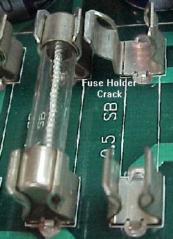
Fuses for the Special Coils.
Each special coil had to have its own fuse to prevent melt-down if the
activating switch got stuck on. These fuses were installed starting
with Monday Night Football. In games Laser War to Playboy, a
fuse holder and a 2.5 amp slo-blo fuse should be installed under the playfield,
to the blue wire for each special coil. This was indicated in DataEast service
bulletin number 20. It also suggested checking that the pop bumper "spoon"
switches were adjusted correctly, the special coils were mounted
tightly in their brackets, and the metal pop bumper "yokes" were not
broken.
Eventually DataEast changed their mind on these "special coils", and made them CPU controlled. DataEast referred to the CPU control of these coils as "non-reflexive" circuitry. This means, regardless of how long a solenoid's switch was closed, the solenoid would be energized only once by the CPU, and for a pre-determined time. With this design, when a switch got stuck closed, the coil would not lock on or "machine gun" and burn (or blow a fuse). DataEast implemented this "non-reflexive" circuit with Version 3 of their CPU board (Back to the Future).
Reversal of the L & R Relay Sides.
On the games Time Machine to Simpsons (seven games), DataEast designed the power distribution
through the PPB's L/R relay (K1) in "reverse". That is, with the relay unenergized,
the "L" side powered the flashlamps instead of the coils. This was
a design error! Often the L/R relay would get cold solder
joints, and simply not work. This meant if a player started a game,
only the flashlamps would light (and the game could not be played).
If the coils were on the "L" side of the relay, at least the game
could be played (or partially played, but without the flashlamps).
This error can not be fixed without changes to the software, and
changes to the wiring (we could change the wiring, but unfortunately we can
not change the game's software).
The other problem with this design presents itself when a TIP122 transistor fails (shorts). If any of the related TIP122 transistors short to ground (leaving a permanent ground path for the related device), that "L" side device will lock on (as soon as power is turned on to the game). In the "normal" design, this meant a coil would lock on. This was good; it would be obvious to the operator, and the coil would draw enough power to blow its associated fuse. However with games Time Machine to Simpsons, the "L" side device was as flashlamp. This would lock on the flashlamp, which did not draw enough power to blow its associated fuse. Worse, these flashlamps would get so hot they could melt playfield plastics!
DataEast realized the error they made, and corrected the design so the "L" side connected to coils (as done previously), and not flashlamps.
More L/R Relay Problems.
In regards to the L/R relay on the PPB board, other
problems can be seen (even on games where the L/R sides
are not reversed). For example, on the 1992 Star Wars game, it
can instantly starts multi-ball mode when a game is started.
Balls just keep popping into the shooter
lane and then are shot onto the playfield.
This is an incredibly common problem, and is very confusing. This problem is nearly always cold solder joints on the "L/R" relay, on the PPB board. Because this relay (when not energized) defaults to activating the solenoids, any attempt by the game to light a flash lamp (for example, when a game is started), will instead activate the associated solenoid. The flasher paired with the ball popper is supposed to light, but instead another ball gets placed in the shooter lane. DataEast's auto-ball-fire games all have a 'lightning ball' feature which automatically launches a ball in the shooter lane onto the playfield. This gives the instant multi-ball. To fix this, check the L/R relay on the PPB board, and resolder the relay's solder joints.
|
This page in the DataEast manuals (in this case, Jurassic Park) is probably the most important page in the manual (the diagram here has been abbreviated for space). It shows the coils/flashlamps and their associated drive transistors. This page is in the "Flash Lamp/Coil Test" section, "Game Diagnostics" chapter. |
|
|
This style coil chart starts appearing around Baywatch. Note the multiplexing coils, and the TIP122 (Q44) and TIP36c (Q5) transistors listed for device 3L. This table was a nice addition to the newer Sega manuals. |

|
- Bank select circuit and bank select relay.
- Bridge rectifiers that supply the solenoid power (previously these bridges were just bolted to the back of the backbox).
- Coil diodes.
- Flashlamp sandstone resistors.
- Solenoid fuses.
- Driver transistors (TIP36c) for the 50 volt devices. Used on the PPB board only (not on MRB board). This eliminated the small SMIG relay boards under the playfield, which controlled the ground switching for the 50 volt coils.
- No more resistive or burnt high voltage EOS switches to weaken the flippers.
- No burnt flipper coils because of a mis-adjusted EOS switch that did not turn off the high-powered side of the flipper coil
- No maintainence of an EOS switch (but an EOS switch was added later).
- Less flipper parts (lower cost).
-
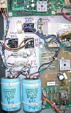
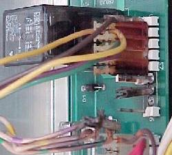
DataEast's MRB/PPB Playfield Power Boards.
MRB and PPB boards were used as intermediate locations for power and ground to be distributed to the playfield for the flashlamps and coils. Laser War and Secret Service used a "MRB" board. The term "MRB" means "Marshmallow Roasting Board". Starting with Torpedo Alley, this board was upgraded and called the "PPB" (officially "Playfield Power Board", but the unofficial name was the "Popcorn Popper Board"). These boards had these nicknames because they could get so hot, marshmallows or popcorn could be cooked on them (this is why cold solder joints are such a problem with these boards). The power boards were used to hold the:
There is really no solution for the heat problems either, other than just being aware of the problem and what it causes (potential cold solder joints).
|
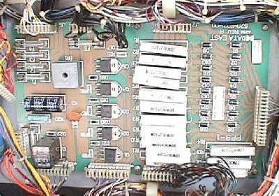
DataEast's PPB board (the equivalent to Williams' Auxiliary Power Driver board). This PPB board is located in the backbox beneath the CPU board. |
|
-
DataEast Flipper Coils - Overview.
Starting with Playboy, DataEast changed from a traditional two winding flipper coil to a single winding flipper coil. This new "Deger design" flipper coil had only two solder lugs, instead of three. The (normally closed) EOS switch now varied the voltage (from 50 volts to 9 volts) going to the flipper coil, instead of changing the overall resistance of the flipper coil (and using a single high voltage). This made the flipper coil design a bit simpler. DataEast did this in preparation for a solid state flipper design.
The DataEast/Sega Solid State Flipper Board.
DataEast was the first company to use solid state flippers
with their 1989 release "RoboCop" (two games after "Playboy").
The concept was simple. After the player pressed the
cabinet flipper switch, turn on the high power voltage to the
flipper coil for only a short, fixed period of time (40 milliseconds).
After 40 ms turn off the high power
and leave the low power on for as long as the player
held the flipper cabinet button.
DataEast/Sega used several different versions of their solid state flipper board. The first version supported just two flippers, and did not use an EOS switch on the flipper coils. Later versions supported two or three flippers and used an EOS switch on the flipper coils.
The advantages of this solid state flipper system were many:
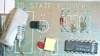
|
The first generation of DataEast's solid state flipper board. They are always located on the side of the cabinet under the playfield. |
|
-
DataEast's solid state flippers were a great idea. However many
players complained that they had a different "feel" to them
(because of the lack of an EOS switch to turn the high powered
side of the flipper coil off). DataEast
changed their solid state flipper design in 1993 with Jurassic Park and
added EOS switches back into the design. The high power was still
turned on for a fixed period of time (40 milliseconds), but now
if the EOS switch was closed again, the flipper board would pulse the
high voltage again. This kept a held flipper in position
if the flipper bat got knocked backwards from a high speed pinball.
Solid State Flipper Board Problems on JP, LAH, TftC.
On the games Jurassic Park, Last Action Hero,
and Tales from the Crypt there is a problem with their flipper board, #520-5033-03 (3 flipper,
as used on JP and TftC) and #520-5070-00 (2 flipper, as used on LAH).
These three games all use a normally closed EOS switch on the two lower flippers (only). If an
EOS switch is broken or mis-adjusted so it is not normally closed, its corresponding
lower flipper will not work! (But the upper flipper, if the game has one,
will continue to work.) This problem was fixed with version #520-5076-00 (3 flippers)
and #520-5080-00 (2 flippers), as used on games Tommy and later.
Also the newer #520-5076-00 and #520-5080-00 are backwards compatible.
The EOS switch was also changed to be more robust on Tales from the Crypt.
This new EOS switch design is easy to identify because of the "bend"
near the end of the switch blade.
Easy Damage to the Solid State Flipper board.
The DataEast solid state flipper board(s) are not in the backbox.
They are located in the lower cabinet, below the playfield. Starting
with Ninja Turtles flipper board damage can occur
because of the board's location (Turtles was the first game with playfield
sliding rails, allowing the playfield to slide forward for easier repair). This happens
when the playfield, in the raised position, gets
tilted, and falls off the cabinet mounting slide rails. This especially
happens if the game's prop rod is used, and the playfield is
not straight on its mounting slide rails.
The best way to avoid damage is to just be careful! When raising the playfield, don't let the playfield get tilted or angled. Also try not to use the playfield prop rod. If it is used, make sure the playfield is straight on the slide rails, and won't fall inside the cabinet.
|
Damage to a solid state flipper board. This happened because the playfield fell off its mounting rails, and damaged the board. This is VERY common. Usually it tears up the flipper board much more than this! Since the SR1 and SR2 transistors with heat sinks stick out the most, they usually get ripped completely off. |
|
1h. Getting Started: Using the Internal Adjustments, Audits & Diagnostics
-
There are two styles of diagnostics used on DataEast and Sega games.
Easy A-Just Diagnostics.
Laser War to Frankenstein used the "Easy A-Just" diagnostic system.
These diagnostics were similar to the type used in Williams'
System 11 games. There were two buttons inside the coin door.
One button is a momentary style (black) switch, the other an up/down (on/off)
style push button (green) switch.
|
The DataEast/Sega "Easy A-Just" diagnostic buttons. |
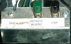
|
-
To enter diagnostics from attract mode, the green up/down button must be
in the "down" position (if this button is "up", the
adjustments/audits will be seen instead).
When this button is in the desired position, press the
black momentary button.
On games before Frankenstein, once in diagnostics, the position of the up/down green button does not matter. The menu items will be stepped through from first to last in sequential order (this was changed for Frankenstein). The position of the green button determines the menu direction the black momentary "step" button will take, either forward or backwards through the menu items. Pressing the black momentary "step" button will move forward through the menu items. If a value is to be changed, press the game's start button. When the desired change is indicated, press the black momentary button to accept the change.
To exit the system, hold the black momentary button down. This will quickly scroll past all the other options. When the end is reached, the game will re-boot.
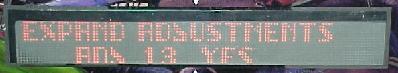
|
There is an adjustment to "expand the adjustments". If free play is desired (or other expanded adjustments), set this option to "yes", and continue scrolling through the adjustments. |
|
-
Adjustments/Audits.
If audits/adjustments is desired, put the green button in the "up" position, and press the black momentary button. Entering changes is the same as described above.
Portals Service Menu.
Starting with Baywatch (the game after Frankenstein), Sega implemented an
icon based "portal" service menu system. This system also
used two buttons, however now both buttons are momentary (Apollo13's Whitestar system
and later used three buttons). To enter the system,
press the black momentary button. The "portals" menu system
will come up on the display.
|
The portals coin door buttons. |
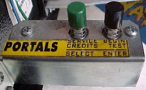
|
-
Once in the portal, use the flipper buttons to move left or right (or the coin door
green momentary button to move right), to navigate from icon to icon. Press the game's start
button (or the black coin door buttom) to select an icon. The "Prev" icon will take
the user back a step, and the "Quit" icon will quit the portal and reboot the game.
|
The portal main menu. |
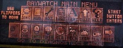
|
-
On early production Baywatch games, the green coin door button was mistakenly
left as an up/down style button. If this button was in the down position, and
the portals was entered via the black momentary button, the menu icons will
continually scroll to the right. To stop this, press the green button into the
up position. This switch can either be replaced or modified to fix this
problem.
To modify the green up/down switch into a momentary switch needed for the portals is simple. Just remove the portals switch bracket from the coin door by removing the two phillips head screws that secure it. On the green button will be a silver "C" shaped wire form. Removing this "C" shaped wire form will convert the switch to a momentary style switch. Use the black momentary switch as a reference, as this switch will not have this "C" shaped wire form. This was mentioned in Sega's service bulletin number 74, and can be viewed here and here.
 �
�